
Page 244 - IJB-8-4
P. 244
3DP PEEK implants for chest wall reconstruction
A B
C
D
E
F G
H
I J K
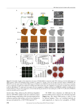
Figure 11. Schematic diagram of the preparation processes of PEEK/additives composites and FDM technology (A); the SEM images of
PEEK granular material (B) and HA powders material (C) (white bar, 100 μm; yellow bar, 50 μm); geometry images of PEEK/HA and
PEEK/CS scaffolds under micro-CT (D); SEM images of PEEK/HA and PEEK/CS scaffolds (E); the comparison of compressive modulus
(F) and compressive strength (G) in PEEK/HA scaffolds with different pore sizes; the comparison of compressive modulus of the PEEK/CS
scaffolds with different CS content and raster angles (H); the comparison of cellular proliferation in PEEK/HA scaffolds with different HA
content (white bar, 400 μm); the comparison of alizarin red staining (J) and Alizarin red staining (K) of MC3T3-E1cells on the PEEK/HA
scaffolds with different HA content [47-49] .
incision ulcer. Thus, enhancing the soft-tissue integration 3D PEEK lattice structures are fabricated by the
with the 3DP PEEK implant is the main method to reduce previous FDM system to observe the soft-tissue ingrowth
implant-related complications. We have developed surface (Figure 9A). The whole FDM process is same as that
amination grafting and sulfuric acid etching methods to for clinical implants. Then, two modified methods are
increase the hydrophilic of 3DP PEEK implants [45-46] . used respectively to improve the hydrophilic of PEEK
236 International Journal of Bioprinting (2022)–Volume 8, Issue 4