
Page 212 - IJB-9-1
P. 212
International Journal of Bioprinting FeS /PCL scaffold for bone regeneration
2
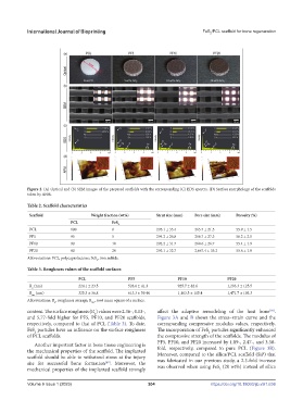
Figure 2. (A) Optical and (b) SEM images of the prepared scaffolds with the corresponding (C) EDS spectra. (D) Surface morphology of the scaffolds
taken by AFM.
Table 2. Scaffold characteristics
Scaffold Weight fraction (wt%) Strut size (mm) Pore size (mm) Porosity (%)
PCL FeS
2
PCL 100 0 295.1 ± 33.4 265.7 ± 21.5 55.9 ± 1.5
PF5 95 5 294.2 ± 26.8 266.7 ± 27.3 56.2 ± 2.1
PF10 90 10 292.2 ± 31.7 268.6 ± 26.7 55.4 ± 1.9
PF20 80 20 293.1 ± 32.7 2,667.4 ± 35.2 55.6 ± 1.8
Abbreviations: PCL, polycaprolactone; FeS , iron sulfide.
2
Table 3. Roughness values of the scaffold surfaces
PCL PF5 PF10 PF20
R (nm) 224.1 ± 23.5 528.6 ± 41.3 925.7 ± 82.6 1,293.3 ± 125.5
a
R (nm) 325.3 ± 36.8 613.3 ± 59.40 1,103.5 ± 115.4 1,471.7 ± 193.3
ms
Abbreviations: R , roughness average; R , root mean square of a surface.
ms
a
content. The surface roughness (R ) values were 2.36-, 4.13-, affect the adaptive remodeling of the host bone .
[50]
a
and 5.77-fold higher for PF5, PF10, and PF20 scaffolds, Figure 3A and B shows the stress–strain curve and the
respectively, compared to that of PCL (Table 3). To date, corresponding compressive modulus values, respectively.
FeS particles have an influence on the surface roughness The incorporation of FeS particles significantly enhanced
2
2
of PCL scaffolds. the compressive strength of the scaffolds. The modulus of
PF5, PF10, and PF20 increased by 1.89-, 2.47-, and 3.38-
Another important factor in bone tissue engineering is
the mechanical properties of the scaffold. The implanted fold, respectively, compared to pure PCL (Figure 3B).
Moreover, compared to the silica/PCL scaffold (SiP) that
scaffold should be able to withstand stress at the injury was fabricated in our previous study, a 2.3-fold increase
[49]
site for successful bone formation . Moreover, the was observed when using FeS (20 wt%) instead of silica
mechanical properties of the implanted scaffold strongly 2
V
Volume 9 Issue 1 (2023)olume 9 Issue 1 (2023) 204 https://doi.org/10.18063/ijb.v9i1.636