
Page 57 - IJB-9-1
P. 57
International Journal of Bioprinting In situ defect detection and feedback control with P-OCT
feedback control after defect detection, which established a P-OCT dataset covered an area of 10 mm (x) × 10 mm
relationship between printed results and the input control (y) × 6.28 mm (z).
parameters. The pre-built feedback mechanism was
mainly aimed at the material deposition errors under three 2.2. In situ defect detection algorithm flow
different paths: the start-stop points, straight path, and For in situ defect detection, layer-by-layer imaging is
turnarounds. After the defects were identified and located, required for large-volume constructs and large-field
the input control parameters were adjusted in time by imaging is essential for defect detection, location,
the pre-built feedback mechanism to ensure the accuracy and feedback. In the previous study , the simplified
[19]
of printing results, and the broken filament defects were iterative closest point algorithm based on a point
repaired with the second printing. In addition to in situ cloud has been proposed to achieve large-field, full-
defect detection and timely feedback control during the depth imaging (Figure S1). This study mainly discusses
extrusion-based printing process, fidelity evaluation can in situ defect detection and feedback control based on
be performed for each layer during the printing process improved quantification methods and a pre-built feedback
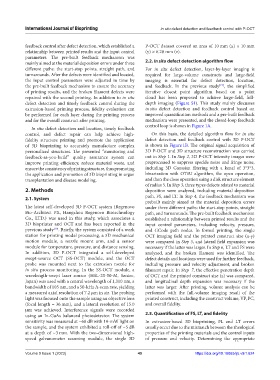
and for the overall construct after printing. mechanism were presented, and the closed-loop feedback
In situ defect detection and location, timely feedback control loop is shown in Figure 1A.
control, and defect repair can help achieve high- On this basis, the detailed algorithm flow for in situ
fidelity structure printing and promote the application defect detection and feedback control with 3D P-OCT
of 3D bioprinting to accurately manufacture complex is shown in Figure 1B. The original signal acquisition of
personalized structures. The presented “monitoring and 3D P-OCT and 3D structure reconstruction was carried
feedback-as-you-build” quality assurance system can out in Step 1. In Step 2, 3D P-OCT intensity images were
improve printing efficiency, reduce material waste, and preprocessed to suppress speckle noise and fringe noise,
ensure the consistency of printing structure, thus promoting including 3D Gaussian filtering with a kenel of 3*3*3,
the application and promotion of 3D bioprinting in organ binarization with OTSU algorithm, the open operation,
transplantation and disease modeling. and then the close operation using a disk structure element
of radius 5. In Step 3, three types defects related to material
2. Methods deposition were analyzed, including material deposition
path, FS, and LT. In Step 4, the feedback mechanism was
2.1. System
prebuilt mainly aimed at the material deposition errors
The latest self-developed 3D P-OCT system (Regenovo under three different paths: the start-stop points, straight
Bio-Architect PX, Hangzhou Regenovo Biotechnology path, and turnarounds. The pre-built feedback mechanism
Co., LTD.) was used in this study, which associates a established a relationship between printed results and the
3D bioprinter and OCT and has been reported in the input control parameters, including velocity, pressure,
previous study [19] . Briefly, the system consisted of a work and GCode path nodes. In formal printing, the single
station for printing model processing, a 3D mechanical OCT imaging field and the printed construct size (x-y)
motion module, a nozzle mount arm, and a sensor were compared in Step 5, and lateral field expansion was
module for temperature, pressure, and distance sensing. necessary if the latter was larger. In Step 6, LT and FS were
In addition, 3D P-OCT integrated a self-developed analyzed, and the broken filament was identified. The
swept-source OCT (SS-OCT) module, and the OCT defect details and locations were used for further feedback,
probe was mounted next to the extrusion nozzle for including pressure and velocity adjustment, and broken
in situ process monitoring. In the SS-OCT module, a filament repair. In Step 7, the effective penetration depth
wavelength-swept laser source (HSL-20-50-M, Santec, of OCT and the printed construct size (z) was compared,
Japan) was used with a central wavelength of 1,310 nm, a and longitudinal depth expansion was necessary if the
bandwidth of 105 nm, and a 50-kHz A-scan rate, yielding latter was larger. After printing, volume analysis can be
a measured axial resolution of 7.2 μm in air. The probing performed with the full-volume imaging result of the
light was focused onto the sample using an objective lens printed construct, including the construct volume, VP, PC,
(focal length = 36 mm), and a lateral resolution of 15.0 and overall fidelity.
μm was achieved. Interference signals were recorded
using an In-GaAs balanced photodetector. The system 2.3. Quantification of FS, LT, and fidelity
sensitivity was measured at ~68 dB with 10-mW light on In extrusion-based 3D bioprinting, FL and LT errors
the sample, and the system exhibited a roll-off of ~5 dB usually occur due to the mismatch between the rheological
at a depth of ~3 mm. With the two-dimensional high- properties of the printing materials and the control inputs
speed galvanometer scanning module, the single 3D of pressure and velocity. Determining the appropriate
Volume 9 Issue 1 (2023) 49 https://doi.org/10.18063/ijb.v9i1.624