
Page 170 - IJB-9-3
P. 170
International Journal of Bioprinting Flow performance of porous implants with different geometry
Figure 3. Shape parameters of structures: (a) OT; (b) G; and (c) P.
assumed that the scaffold wall was hydrophilic with no slip
condition. Meanwhile, an inlet velocity (v = 1 mm/s) at the
inlet-flow side and an output pressure (1 atm pressure) at the
outlet-flow side were set as same boundary conditions in all
scaffolds. As an incompressible and continuous Newtonian
fluid, DMEM was a common medium material, and these
boundary conditions were chosen to simulate in vitro cell
culture. The continuity equation used in the calculation is
given in Equation IV:
∂ρ + div( ρv)0 (IV)
=
∂t
Where v is the flow velocity varying with the time t; ρ is the
density of DMEM. Besides, the governing equation underlying
the calculation is the Navier–Stokes formula, which is an
equation of motion to describe the momentum conservation
of a viscous incompressible fluid in CFD, and conventionally
expressed as Equation V without external force:
1
∂v + v( ⋅∇ v) = −∇ +ρ µ ∇ v (V)
2
∂t ρ ρ
Where μ denotes the dynamical viscosity of DMEM, which
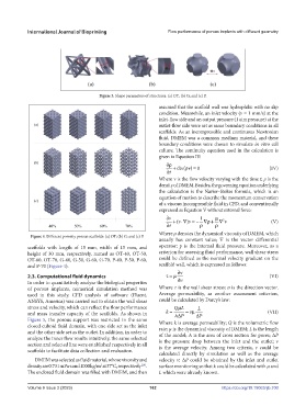
Figure 4. Different porosity porous scaffolds: (a) OT; (b) G; and (c) P.
usually has constant value; ∇ is the vector differential
scaffolds with length of 15 mm, width of 15 mm, and operator; p is the internal fluid pressure. Moreover, as a
height of 30 mm, respectively, named as OT-40, OT-50, criterion for assessing fluid performance, wall shear stress
OT-60, OT-70, G-40, G-50, G-60, G-70, P-40, P-50, P-60, could be defined as the normal velocity gradient on the
and P-70 (Figure 4). scaffold wall, which is expressed as follows:
∂v
2.3. Computational fluid dynamics τ = µ (VI)
In order to quantitatively analyze the biological properties ∂n
of porous implants, numerical simulation method was Where τ is the wall shear stress; n is the direction vector.
used in this study. CFD analysis of software (Fluent, Average permeability, as another assessment criterion,
ANSYS, America) was carried out to obtain the wall shear could be calculated by Darcy’s law:
stress and velocity, which can reflect the flow performance QL L
µ
and mass transfer capacity of the scaffolds. As shown in k = AP = vµ ∆ P (VII)
∆
Figure 5, the porous support was restricted in the same Where k is average permeability; Q is the volumetric flow
closed cuboid fluid domain, with one side set as the inlet rate; μ is the dynamical viscosity of DMEM; L is the length
and the other side set as the outlet. In addition, in order to of the model; A is the area of cross section for pores; ΔP
analyze the inner flow results intuitively, the same selected is the pressure drop between the inlet and the outlet; v
section and selected line were established respectively in all is the average velocity. Among two criteria, τ could be
scaffolds to facilitate data collection and evaluation. calculated directly by simulation as well as the average
DMEM was selected as fluid material, whose viscosity and velocity v; ΔP could be obtained by the inlet and outlet
density are 0.731 mPa⋅s and 1000 kg/m at 37°C, respectively . surface monitoring so that k could be calculated with μ and
3
[29]
The enclosed fluid domain was filled with DMEM, and then L which were already known.
Volume 9 Issue 3 (2023) 162 https://doi.org/10.18063/ijb.700