
Page 219 - IJB-9-4
P. 219
International Journal of Bioprinting Simulation-based comparative analysis of nozzles for bioprinting
them are the material used, i.e., plastic for the conical tip
and brass/stainless steel for the nozzle, and their internal
geometry, which can be seen in Figure 2. Typically, the
conical tip is optimized for its use in clinical work with
low-viscosity materials. On the contrary, 3D printing
nozzles are designed and manufactured to reduce the force
needed to work with molten plastics, which are considered
high-viscosity materials. Nevertheless, to the best of our
knowledge, no studies have been performed to analyze
the performance of standard 3D printing nozzles with
bioprinting materials.
Hence, the working hypothesis is that a standard 3D
printing nozzle could improve performance of a conical tip
standard bioprinting nozzle. Consequently, the objective
of this work is to analyze the performance of an E3D V6
standard nozzle compared with a 22G conical tip for a
microextrusion bioprinting process using a commercial
bioink as hydrogel. Specifically, inlet (or dispensing)
and outlet pressure, volumetric flow, outlet velocity
and maximum shear stress were analyzed. To study the
feasibility of the proposed nozzle, two different simulation
inlets were configured to simulate pneumatic and piston-
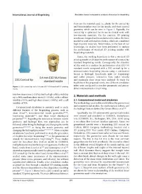
Figure 1. 22G conical tip and a 0.4 mm E3D V6.4 standard 3D printing
nozzle. driven microextrusion bioprinting.
into low shear stress (<5 kPa), that has high cellular viability 2. Materials and methods
up to 96%; medium shear stress (5–10 kPa), with a cellular
viability of 91%; and high shear stress (>10 kPa), with a cell 2.1. Computational model and simulation
viability of 76%. The methodology used in this work follows the geometrical
and computational models, the mathematical solvers, and
Computational simulation is currently used to study [50]
different features of the bioprinting process, such as the hydrogel features defined by Gómez-Blanco et al.
shear stress , noncommercial nozzle geometries [40-42] , Specifically, two 2D axisymmetric geometrical models
[39]
bioprinting materials , and their tuned rheological were created and simulated in COMSOL Multiphysics
[43]
properties [37,44] . Regarding the interaction between nozzle 5.4a (COMSOL Inc., Burlington, MA, USA, 2018) using
geometry and hydrogel flow, two approaches can be a two-phase flow level-set interface approach. These two
followed: either fixing the hydrogel and changing the nozzle geometrical models were a bioprinting 22G conical tip
geometries [25,41,42,45] or fixing the nozzle geometry and (Cellink, BICO Company, Gothenburg, Sweden) and a
changing the hydrogel properties [37,39,43,46-48] . More complex 3D printing E3D V6.4 nozzle (E3D Online, Chalgrove,
simulations have been performed to study the generation Oxfordshire, UK), named hereinafter as Cone and Nozzle,
of droplets for inkjet bioprinting [47,49] or the generation of respectively. The geometries were chosen for two main
strands for microextrusion bioprinting . These studies reasons. The first is that 0.4 mm is the most common
[50]
used the two-phase flow level-set model in COMSOL gauge/diameter for both printheads. The second is related
multiphysics to simulate the bioprinting process. On the one to the different overall lengths of the nozzle and tip, and
[47]
[49]
hand, results from Liravi et al. and Samanipour et al. the different lengths and angles of the internal tapered
showed an experimentally tested droplet generation using a wall. Fluid dynamics theory suggests that straight tubes
[50]
27G conical tip. On the other hand, Gómez-Blanco et al. have a constant distribution of shear stress in the wall. On
studied some inner parameters of the microextrusion the other hand, abrupt changes in the wall angle cause a
process (shear stress, pressure, and velocity), but without distortion of the shear stress distribution and values. The
experimental validation. Finally, other simulation studies geometries were obtained by experimental measurement
analyzed the flow through a standard 3D printing nozzle for the Cone and from blueprints for the Nozzle . In
[53]
and the filament deposition in a fuse deposition modeling Figure 2, blueprint cross sections of both geometries (A)
process [51,52] . Figure 1 shows both a 22G conical tip and a are shown for better understanding of the modeled inner
standard 3D printing nozzle. The main differences between geometries used in the simulations.
Volume 9 Issue 4 (2023) 211 https://doi.org/10.18063/ijb.730