
Page 311 - IJB-9-5
P. 311
International Journal of Bioprinting Scaffold for engineering enthesis organ
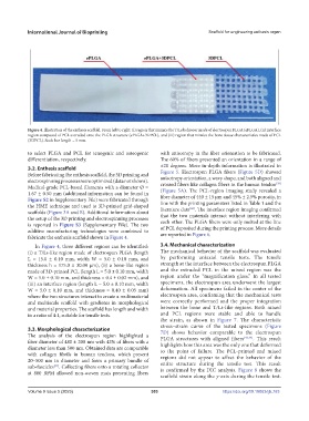
Figure 4. Illustration of the enthesis scaffold. From left to right: (i) region that mimics the T/Ls behavior made of electrospun PLGA (ePLGA), (ii) interface
region composed of PCL extruded onto the PLGA structure (ePLGA+3DPCL), and (iii) region that mimics the bone tissue characteristics made of PCL
(3DPCL). Scale bar length = 5 mm.
to select PLGA and PCL for tenogenic and osteogenic with anisotropy in the fiber orientation to be fabricated.
differentiation, respectively. The 60% of fibers presented an orientation in a range of
±20 degrees. More in-depth information is illustrated in
3.2. Enthesis scaffold
Before fabricating the enthesis scaffold, the 3D printing and Figure 5. Electrospun PLGA fibers (Figure 5D) showed
electrospinning processes were optimized (data not shown). anisotropy orientation, a wavy shape, and both aligned and
[29]
Medical-grade PCL-based filaments with a diameter Ø = crossed fibers like collagen fibers in the human tendon
1.67 ± 0.50 mm (additional information can be found in (Figure 5A). The PCL-region imaging study revealed a
Figure S2 in Supplementary File) were fabricated through fiber diameter of 440 ± 15 µm and 45% ± 2.5% porosity, in
the HME technique and used to 3D-printed grid-shaped line with the printing parameters listed in Table 1 and the
[42]
scaffolds (Figure 3A and B). Additional information about literature data . The interface region imaging confirmed
the setup of the 3D printing and electrospinning processes that the two materials interact without interfering with
is reported in Figure S3 (Supplementary File). The two each other. The PLGA fibers were only melted at the line
additive manufacturing technologies were combined to of PCL deposited during the printing process. More details
fabricate the enthesis scaffold shown in Figure 4. are reported in Figure 6.
In Figure 4, three different regions can be identified: 3.4. Mechanical characterization
(i) a T/Ls-like region made of electrospun PLGA (length The mechanical behavior of the scaffold was evaluated
L = 15.0 ± 0.10 mm, width W = 5.0 ± 0.10 mm, and by performing uniaxial tensile tests. The tensile
thickness h = 175.0 ± 30.00 µm), (ii) a bone-like region strength at the interface between the electrospun PLGA
made of 3D-printed PCL (length L = 5.0 ± 0.10 mm, width and the extruded PCL in the mixed region was the
W = 5.0 ± 0.10 mm, and thickness = 0.4 ± 0.02 mm), and region under the “magnification glass.” In all tested
(iii) an interface region (length L = 5.0 ± 0.10 mm, width specimens, the electrospun area underwent the largest
W = 5.0 ± 0.10 mm, and thickness = 0.40 ± 0.05 mm) deformation. All specimens failed in the center of the
where the two structures interact to create a multimaterial electrospun area, confirming that the mechanical tests
and multiscale scaffold with gradients in morphological were correctly performed and the proper integration
and material properties. The scaffold has length and width between the bone and T/Ls-like regions. Both mixed
in a ratio of 4:1, suitable for tensile tests. and PCL regions were stable and able to handle
the strain, as shown in Figure 7. The characteristic
stress–strain curve of the tested specimens (Figure
3.3. Morphological characterization 7D) shows behavior comparable to the electrospun
The analysis of the electrospun region highlighted a PLGA structures with aligned fibers [43,44] . This result
fiber diameter of 480 ± 200 nm with 42% of fibers with a highlights how this area was the only one that deformed
diameter less than 500 nm. Obtained data are comparable to the point of failure. The PCL-printed and mixed
with collagen fibrils in human tendons, which present regions did not appear to affect the behavior of the
20–500 nm in diameter and form a primary bundle of entire structure during the tensile test. This result
sub-fascicles . Collecting fibers onto a rotating collector is confirmed by the DIC analysis. Figure 8 shows the
[41]
at 800 RPM allowed non-woven mats presenting fibers
scaffold strain along the y-axis during the tensile test.
Volume 9 Issue 5 (2023) 303 https://doi.org/10.18063/ijb.763