
Page 55 - IJB-9-5
P. 55
International Journal of Bioprinting Precise fabrication of engineered vascular networks
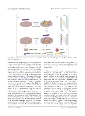
Figure 7. Schematic diagram of the preparation of in vitro model with hierarchical vasculature for studying the interaction between HUVECs and OCs.
Created with BioRender.com.
extracted from the sacrificed mice. First, no inflammation experiments were prepared without cells. However, the
or abnormalities were found in the surrounding tissues host vessels within the engineered vasculature, which
in all the groups after 4 weeks of implantation, indicating have a great potential for anastomosis, will be a focus for
the good biocompatibility of the P/G hydrogel scaffolds. further study.
More blood vessels were observed around the scaffolds
with vasculature compared with the control group’s H&E and Masson’s trichrome staining images are
scaffolds. Blood was observed in the vasculature within the displayed in Figure 9B and C. No new tissues or red
1 × 1, 4 × 4, and 8 × 8 scaffolds in the gross observation blood cells were formed in the center of the control
images, as shown in Figure 9A. The number of vascular group’s scaffolds. In the scaffolds with vasculature, all
branches and the vascular length around the scaffolds hollow channels of the vasculature were fully filled with
were calculated (Figure S11 in Supplementary File). The new tissue after the implantation. Magnified images
number of branches around the 4 × 4 and 8 × 8 scaffolds of the vasculature lumens within 1 × 1, 4 × 4, and 8 × 8
was 18 ± 1.0 and 24 ± 7.8, respectively, which was scaffolds are displayed in Figure 9E(i)–(iii), respectively.
considerably higher than the number of branches found Red blood cells were visible within the vasculature lumens.
around the control group’s scaffold and 1 × 1 scaffold Immunofluorescence staining of CD31 and α-SMA was
(Figure S11A in Supplementary File). The vascular conducted to further confirm the formation of vessels in
length around the scaffolds increased with the increase in the engineered vasculature (Figure 9D). Magnified images
vascular density (Figure S11B in Supplementary File). The of the vasculature lumens within 1 × 1, 4 × 4, and 8 × 8
results demonstrated that the scaffolds with engineered scaffolds are displayed in Figure 9F(i)–(iii), respectively.
vasculature can promote the blood vessel infiltration and Vascular structures were found to be densely distributed
growth of neighboring host vessels in the surrounding in the 8 × 8 scaffold group (Figure 9F(iii)). Although the
tissues. This is mainly due to the mass transport function expression of α-SMA could be detected in the vasculature
of the fabricated vasculature within the P/G hydrogel lumens within the 1 × 1 and 4 × 4 scaffolds, no complete
scaffolds. To demonstrate that the host vessels can grow circular structure of α-SMA was observed (Figure 9F(i)
into the prepared vasculature, the scaffolds used for animal and (ii)). The results suggest that the engineered
Volume 9 Issue 5 (2023) 47 https://doi.org/10.18063/ijb.749