
Page 24 - IJB-9-6
P. 24
International Journal of Bioprinting CFD analysis for multimaterial bioprinting conditions
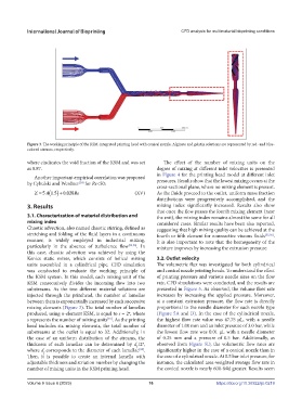
Figure 3. The working principle of the KSM-integrated printing head with conical nozzle. Alginate and gelatin solutions are represented by red- and blue-
colored streams, respectively.
where εindicates the void fraction of the KSM and was set The effect of the number of mixing units on the
as 0.87. degree of mixing at different inlet velocities is presented
Another important empirical correlation was proposed in Figure 4 for the printing head model at different inlet
by Cybulski and Werdner for Re<50: pressures. Results show that the lowest mixing occurs at the
[54]
cross-sectional plane, where no mixing element is present.
Z 54. 15. 0 028. Re (XV) As the fluids proceed to the outlet, uniform mass fraction
distributions were progressively accomplished, and the
3. Results mixing index significantly increased. Results also show
that once the flow passes the fourth mixing element (near
3.1. Characterization of material distribution and the exit), the mixing index remains almost the same for all
mixing index considered cases. Similar results have been also reported,
Chaotic advection, also named chaotic stirring, defined as suggesting that high mixing quality can be achieved at the
stretching and folding of the fluid layers in a continuous fourth or fifth element for nonreactive viscous fluids [55,56] .
manner, is widely employed in industrial mixing, It is also important to note that the homogeneity of the
particularly in the absence of turbulence flow [35,36] . In mixture improves by increasing the extrusion pressure.
this case, chaotic advection was achieved by using the
Kenics static mixer, which consists of helical mixing 3.2. Outlet velocity
units assembled in a cylindrical pipe. CFD simulation The volumetric flux was investigated for both cylindrical
was conducted to evaluate the working principle of and conical nozzle printing heads. To understand the effect
the KSM system. In this model, each mixing unit of the of printing pressure and various needle sizes on the flow
KSM consecutively divides the incoming flow into two rate, CFD simulations were conducted, and the results are
substreams. As the two different material solutions are presented in Figure 5. As observed, the volume flow rate
injected through the printhead, the number of lamellae increases by increasing the applied pressure. Moreover,
between them is exponentially increased by each successive at a constant extrusion pressure, the flow rate is directly
mixing elements (Figure 3). The total number of lamellas proportional to the needle diameter for each nozzle type
produced, using n-element KSM, is equal to s = 2 , where (Figure 5A and D). In the case of the cylindrical nozzle,
n
s represents the number of mixing units . As the printing the highest flow rate value was 47.75 µL, with a needle
[15]
head includes six mixing elements, the total number of diameter of 1.00 mm and an inlet pressure of 3.0 bar, while
substreams at the outlet is equal to 32. Additionally, in the lowest flow rate was 0.01 µL with a needle diameter
the case of an uniform distribution of the streams, the of 0.25 mm and a pressure of 0.5 bar. Additionally, as
thickness of each lamellae can be determined by d /2 , observed from Figure 5D, the volumetric flow rates are
n
f
where d corresponds to the diameter of each lamellae . significantly higher in the case of a conical nozzle than in
[28]
f
Then, it is possible to create an internal lamella with the case of a cylindrical nozzle. At 0.5 bar inlet pressure, for
adjustable thickness and striation number by changing the instance, the calculated area-weighted average flow rate in
number of mixing units in the KSM printing head. the conical nozzle is nearly 600-fold greater. Results seem
Volume 9 Issue 6 (2023) 16 https://doi.org/10.36922/ijb.0219