
Page 28 - IJB-9-6
P. 28
International Journal of Bioprinting CFD analysis for multimaterial bioprinting conditions
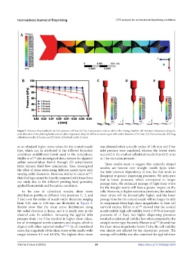
Figure 7. Pressure drop results for an inlet pressure of 1 bar. (A) The local pressure contour plot in the mixing chamber. (B) Variation of pressure along the
axial direction of the printing head; contour plots of pressure drop for different nozzle types with outlet diameter of 0.4 mm. (C) Conical needle, (D) long
cylindrical needle (12 mm), and (E) short cylindrical needle (5 mm).
as we obtained higher stress values for the conical nozzle was obtained when a needle radius of 1.00 mm and 3 bar
type, which can be attributed to the different boundary inlet pressure were employed, whereas the lowest stress
conditions anddifferent bioink used in the simulations. occurred in the smallest cylindrical needle flow (0.25 mm)
Muller et al. also investigated shear stresses for alginate/ at 1 bar extrusion pressure.
[32]
sulfate nanocellulose bioink through 2D axisymmetric These results seem to suggest that conically shaped
finite element fluid flow simulations. They investigated needles are favored over straight needle types when
the effect of shear stress using different nozzle types with the inlet pressure dependency is low, but this tends to
varying outlet diameters. However, similar to Liu et al. , disappear at greater dispensing pressures. We anticipate
[65]
their findings cannot be directly compared with those from that at lower pressures, which correspond to longer
our study due to the different printing head geometry, passage time, the enhanced passage of high shear stress
applied biomaterials and boundary conditions.
for the straight nozzle will have a greater impact on the
In the case of cylindrical nozzles, shear stress cells. However, at higher extrusion pressures, the induced
distribution profiles at different inlet pressures (1, 2, and shear stress will be dramatically higher, and the lower
3 bar) over the radius of nozzle outlet diameters ranging passage time for the conical nozzle will no longer be able
from 0.25 mm to 1.00 mm are illustrated in Figure 9. to compensate these high shear magnitudes. In their cell
Results show that the shear stress distribution along survival studies, Billiet et al. showed that the conical
[34]
the radial direction is linear, and it is nearly zero in the nozzle exhibit high cell viability levels (>97% at low inlet
channel core. In addition, increasing the applied inlet pressures of <1 bar), but higher dispensing pressures
pressure from 1 to 3 bar resulted in higher shear values, resulted in substantial viability loss when compared to the
for all investigated nozzle diameters and shapes, which is straight nozzle type. Recently, Blaeser et al. showed that
[66]
aligned with other reported studies [32,33] . In all considered for shear stress magnitudes below 5 kPa, the cell viability
cases, the magnitude of the shear stress at the needle walls was almost not affected by the deposition process. The
ranges between 0.5 and 4.8 kPa. The highest shear stress average cell viability was also examined for applied shear
Volume 9 Issue 6 (2023) 20 https://doi.org/10.36922/ijb.0219