
Page 27 - IJB-9-6
P. 27
International Journal of Bioprinting CFD analysis for multimaterial bioprinting conditions
related hydrodynamic resistance against the material flow,
which requires higher dispensing pressures. Applying high
pressures at the inlets can have a detrimental impact on the
cell viability, also requiring the use of systems with more
powerful pumps . Nair et al. also observed that the
[61]
[28]
use of a nozzle tip, with a diameter of 0.15 mm and high
extrusion pressure (40 psi≈ 2.75 bar), resulted in karyolysis
as well as pyknosis.
3.4. Shear stress
The level of shear stress was carefully investigated in terms
of key printing parameters, such as nozzle type, dispensing
pressure, and needle diameter. Since the simulations were
conducted for the entire printing head, the shear stress
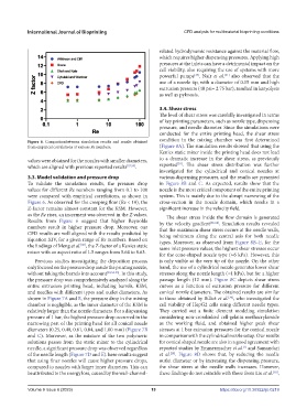
Figure 6. Comparisonbetween simulation results and results obtained condition in the mixing chamber was first determined
from empirical correlations at various Re numbers. (Figure 8A). The simulation results showed that using the
Kenics static mixer inside the printing head does not lead
values were obtained for the nozzles with smaller diameters, to a dramatic increase in the shear stress, as previously
[28]
which are aligned with previous reported results [57,59] . reported . The shear stress distribution was further
investigated for the cylindrical and conical nozzles at
3.3. Model validation and pressure drop various dispensing pressures, and the results are presented
To validate the simulation results, the pressure drop in Figure 8B and C. As expected, results show that the
values for different Re numbers ranging from 0.1 to 100 nozzle is the most critical component of the entire printing
were compared with empirical correlations, as shown in system. This is mainly due to the abrupt narrowing of the
Figure 6. As observed for the creeping flow (Re < 10), the cross-section in the nozzle domain, which results in a
Z-factor remains almost constant for the KSM. However, significant increase in the velocity field.
as the Re rises, an increment was observed in the Z values. The shear stress inside the flow domain is generated
Results from Figure 6 suggest that higher Reynolds by the velocity gradient [62-64] . Simulation results revealed
numbers result in higher pressure drop. Moreover, our that the maximum shear stress occurs at the needle walls,
CFD results are well aligned with the results predicted by being minimum along the central axis for both needle
Equation XIV, for a given range of Re numbers. Based on types. Moreover, as observed from Figure 8B–E, for the
the findings of Meng et al. , the Z-factor of a Kenics static same inlet pressure values, the highest shear stresses occur
[60]
mixer with an aspect ratio of 1.5 ranges from 5.64 to 8.63. for the cone-shaped nozzle type (≈6 kPa). However, this
Previous studies investigating the deposition process is only visible at the very tip of the nozzle. On the other
only focused on the pressure drop inside the printing nozzle, hand, the use of a cylindrical nozzle generates lower shear
without taking the barrels into account [30,54-55] . In this study, stresses along the nozzle length (≈1 kPa), but for a higher
the pressure drop was comprehensively analyzed along the passage length (12 mm). Figure 8C depicts shear stress
entire extrusion printing head, including barrels, KSM, curves as a function of extrusion pressure for different
and needles with different types and outlet diameters. As conical nozzle diameters. The obtained results are similar
shown in Figure 7A and B, the pressure drop in the mixing to those obtained by Billiet et al. , who investigated the
[34]
chamber is negligible, as the inner diameter of the KSM is cell viability of HepG2 cells using different needle types.
relatively larger than the nozzle diameters. For a dispensing They carried out a finite element modeling simulation
pressure of 1 bar, the highest pressure drop occurred in the considering non-crosslinked cell-gelatin methacrylamide
narrowing part of the printing head for all conical nozzle as the working fluid, and obtained higher peak shear
diameters (0.25, 0.40, 0.61, 0.84, and 1.00 mm) (Figure 7B stresses at 1 bar extrusion pressures for the conical nozzle
and C). Moreover, as the mixture of the two polymeric in comparisonwith the cylindrical nozzle setup. Our results
solutions passes from the static mixer to the cylindrical for conical shaped nozzle are also in a good agreement with
needle, a significant pressure drop was observed regardless reported studies by Emmermacher et al. and Samandari
[1]
of the needle length (Figure 7D and E). hese results suggest et al. . Figure 8D shows that, by reducing the needle
[28]
that using finer nozzles will cause higher pressure drops, outlet diameter or by increasing the dispensing pressure,
compared to nozzles with larger inner diameters. This can the shear stress at the needle walls increases. However,
[65]
be attributed to the energy loss, caused by the wall-channel- these findings do not coincide with those from Liu et al. ,
Volume 9 Issue 6 (2023) 19 https://doi.org/10.36922/ijb.0219