
Page 67 - IJB-9-6
P. 67
International Journal of Bioprinting 3D Aerosol Jet® printing for microstructuring
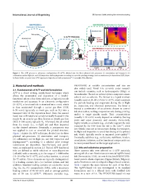
Figure 1. The AJ®P process in ultrasonic configuration (U-AJ®P), divided into the three physical sub-processes: (i) atomization and transport, (ii)
collimation and in-flight jet, and (iii) impaction and impingement according to a specific printing strategy, such as continuous jet deposition (CJD), layer-
[56]
by-layer (LBL), or point-wise (PW) approach. Reproduced with permission , Copyright 2022, Elsevier.
2. Material and methods PEDOT:PSS) at variable concentration and size are
also widely used. Novel inks currently under research
2.1. Fundamentals of AJ P and ink formulation can include ceramics, such as hydroxyapatite (HAp), or
®
AJ®P is a direct writing, nozzle-based technique which biomolecules. The ink co-solvent system comprises a main
allows the atomization and deposition of a (multi)- solvent and co-solvents. The former is a liquid medium
functional ink on a free-form substrate, at high microscale (usually water at 20–60 v/v% for U-AJ®P), which suspends
resolutions and accuracy. In an ultrasonic configuration the particle loading and evaporates during the in-flight
(U-AJ®P), a functional ink is atomized into a mist, which jet, impaction, and (thermal) postprocess. The latter is
is then accelerated through a carrier gas flow (CGF, instead a combination of co-solvents chosen to control
0–50 sccm) (generally an inert gas, such as N ) into a ink atomization, wetting, evaporation rate during printing,
2
transport tube till the deposition head. Here, the aerosol and/or to target specific needs. Their concentrations
beam was collimated and aerodynamically focused in the (usually 5–20 v/v%) mostly depend on volatility (boiling
nozzle by an annular gas flow, known as sheath gas flow point and vapor pressure), and viscosity. Particularly,
(SGF, 0–200 sccm), typically N . Afterward, the jet exited highly volatile co-solvents (e.g., alcohols) support the mist
2
from the nozzle (i.e., in-flight jet) and then impacted transport by the CGF from the vial to the tube , while
[35]
on the desired substrate. Eventually, a postprocess step less volatile ones act as humectants during the transport,
was applied to cure or crosslink the printed structure. in-flight and impaction to avoid fast drying of the printed
Figure 1 depicts the AJ®P technique, divided into its three ink, which typically results in impaired print-quality .
[33]
physical sub-processes: (i) atomization and transport, Eventually, additives (e.g., surfactants, stabilizers, binders,
(ii) collimation and in-flight jet, and (iii) impaction and crosslinkers, initiators, and/or functional compounds) can
impingement , according to a selected print strategy be incorporated based on the target application.
[33]
(continuous jet deposition, layer-by-layer, and point-
wise), as explained in section 2.3. Typical AJ®P functional 2.2. Inks and substrates preparation
inks are defined as stable solutions or nano-dispersions Three aqueous inks were selected as U-AJ®P materials,
(colloids) with a viscosity, η, in the range of 1–1000 mPas among which a non-Newtonian commercial AgNPs-based
(10–20 mPas for U-AJ®P), and surface tension, σ, around ink (Novacentrix, USA), an own-formulated PEDOT:PSS-
20–75 mN/m. Three elements are typically distinguished: based pseudo-elastic dispersion (Sigma Aldrich, Belgium),
(i) a loading content, (ii) a (co-)solvent system, and (iii) and a Newtonian own-developed collagen-based solution.
additives. Standard loading contents are conductive metal Table 1 reports the main features for each of the fluid.
(Ag, Cu, Au, Pt) nanoparticles (NPs), with a maximum The AgNPs-based ink was investigated in its standard
loading content of 40–60 wt.% and an average particle formulation and in a diluted form with distilled (DI)
size of 50 nm (U-AJ®P) . Polymeric particles (e.g., water, in a ratio of 1:4. The PEDOT:PSS-based ink was
[34]
Volume 9 Issue 6 (2023) 59 https://doi.org/10.36922/ijb.0257