
Page 72 - IJB-9-6
P. 72
International Journal of Bioprinting 3D Aerosol Jet® printing for microstructuring
®
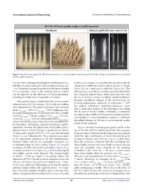
3D-LBL AJ P poor quality results on AgNPs-based ink
Not diluted Diluted (AgNPs:DI water ratio of 1:4)
a b c d
500 µm
250 µm 100 µm 250 µm
Figure 3. Results for poor-quality 3D AJ®P microstructures (6 × 4 array) for AgNPs-based ink using the 3D-LBL strategy. (a) Nondiluted and (c, d) diluted
3D-LBL AgNPs-based ink.
branch, which subsequently divided in multibranches (i.e., is plane and compact, it is possible that sometimes the tip
leaf-like structure) during the CJD printing (printing time can present a hollowed structure (inner diameter < 20 µm,
< 3 s). However, the more branches it is, the more complex Figure 2d ) or a mark-up on a left side (Figure 2d ). This
1
3
it is to reproduce them in the meaning that no control discrepancy is caused by an unstable aerosol jet deposition
can be imposed on the direction of branch generation, rate along the printed layers, which may vary over time
resulting in similar, but not repeatable, structures. due to an intrinsic process variability caused by thermo-
Alternatively, Figure 2c and d show 3D microstructures dynamic equilibrium changes of the aerosol along the
achieved with a 3D-LBL strategy. All 3D-LBL micropillars printing subprocesses, especially in subprocess 1. AJ®P
were obtained when the platen temperature was increased has indeed well-known variability/consistency issues
from T CJD, AgNPs = 40°C to T LBL, AgNPs = 100°C, initiating an in- and a quantitative analysis of the deposition rate change
loco presintering process. Compared to 3D-CJD, a smaller will be part of further studies. Eventually, a substantial
nozzle Ø LBL, AgNPs = 100 μm, a higher CGF LBL, AgNPs = 18 sccm, overspray is also visible at the bottom of the printed pillars.
a lower R , = 1.67 and a lower print speed, s LBL, AgNPs = Accordingly, it is recommended to maintain a minimum
f LBL, AgNPs
0.4 mm/sec, are selected to obtain the most controllable LBL interpillars distance of 200 µm to avoid material overlap
jet deposition. Particularly, using the nondiluted AgNPs- caused by the overspray.
based ink, frost/tree-like pillars (row of five pillars) with a Figure 3 instead illustrates poor quality results in the
diameter base of 110.39 ± 9.82 µm, a tip diameter of 18.99 ± use of 3D-LBL AJ®P for AgNPs-based ink. This sequence
2.18 µm, and a height of 955.79 ± 15.17 µm, were obtained of figures aims to demonstrate the importance to properly
(Figure 2c, see Videoclip S1). These structures are easier select the right combination of (non)-diluted ink, print
to be reproduced compared to 3D-CJD multibranches; parameter window, and CAD file. Figure 3a and b show
however, better defined and repeatable structures can frost-like structures obtained with the nondiluted ink.
be obtained when the ink is diluted (Figure 2d). In such These highly porous structures (high overspray present
condition, 3D-LBL rows (such as six pillars, Figures 2d ) onto the substrate) were obtained by dry printing
1-2
or arrays (such as 6 × 4, Figures 2d ) of vertically aligned a doubled CAD circle (Ø = 100 µm), a print nozzle
3-4
micropillars can be easily disposed. The average height three times higher than the previous one (Ø LBL, AgNPs =
is 960.42 ± 37.69 µm (equal to 50 printed layers), the 300 μm), and a speed almost 17 times faster (s LBL, AgNPs =
diameter is 47.74 ± 5.62 µm (uniform along the z-axis), the 7 mm/s). Moreover, by changing the R , LBL, AgNPs from
f
AR is ca. 20 (Figure 2d ), and the printing time is ~ 5 min. 2 to 4, that is CGF LBL, AgNPs = 20 sccm and SGF LBL, AgNPs
3
In this case, optical and SEM images show that the printed from 40 (Figure 3a) to 80 sccm (Figure 3b), a drastic
pattern is clearly visible, with a growth rate of ~ 8 ± 1 µm/ pillar overlapping is visible. This is due to the effect of
layer. Particular attention should be given to the tip of the the SGF, which deviates the aerosol jet impingement on
pillars: if in general the tip is depicted as in Figure 2d , that the substrate, producing waved and overlapped frost-like
4
Volume 9 Issue 6 (2023) 64 https://doi.org/10.36922/ijb.0257