Page 11 - IJOCTA-15-2
P. 11

M. Perala, S. Chandrasekaran, E. Begovic / IJOCTA, Vol.15, No.2, pp.202-214 (2025)
                    Table 1. Geometric parameters

                     Design particular                          Notation Magnitude            Unit
                     Length overall (m)                            LOA           231.50         m
                     Length between perpendiculars                 LBP            210.0         m
                     Design beam                                     B            36.0          m
                     Design draft or operating draft               Deep           11.5          m
                     Lightship draft                               Tight           8.5          m
                     Molded depth                                  D mld          17.8          m
                     Displacement                                    ∆           50,579      tonnes
                     Displaced volume                                ∇           49,349        m 3
                     Length on waterline                           L WL          223.47         m
                     Beam on waterline                             B WL           31.68         m
                     Position of moonpool from transom               P           103.35         m
                     Moonpool length                                 L            24.8          m
                     Moonpool breadth                                B            12.8          m
                     Cutout slant angle                              α             90           ◦
                     Waterplane area                               A WP          5,959.6       m 2
                     Wetted surface area                          A wetted       10,026        m 2
                     Longitudinal CoG                               X G           105           m
                     Transverse CoG                                 Y G             0           m
                     Vertical CoG                                   Z G           15.13         m
                     Radius of gyration about X                    K XX           12.6          m
                     Radius of gyration about Y                     K yy        104.175         m
                     Radius of gyration about Z                     K ZZ        104.175         m
                     Abbreviation: CoG: Center of gravity.

                                                              and represented by the JONSWAP spectrum,     15
                                                              featuring a peakedness parameter of 3.3. The ex-
                                                              ample plot (Figure 6) shows the JONSWAP spec-
                                                              trum for an irregular wave with a height of 5 m
                                                              and a period of 10 s. The JONSWAP spectrum
                                                              was selected for this analysis as it accounts for
                                                              the energy imbalance in waves, typical of seas
                                                              that are not fully developed. It makes the JON-
                                                              SWAP spectrum especially suitable for simulating
                                                              realistic offshore conditions. By incorporating the
                                                              JONSWAP spectrum, the study ensures that the
                                                              wave conditions closely mimic irregular sea states,
                                                              creating a robust testing environment to evaluate
                                                              the AI algorithm’s performance.
            Figure 4. Wave directions
            Abbreviation: SB: Starboard

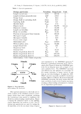
                This approach guarantees a thorough and re-
            alistic analysis of the drillship’s dynamic perfor-
            mance across these wave conditions, providing
            the foundational data needed to implement the
            AI-driven station-keeping control system. Figure
            5 depicts the numerical model of the drillship,
            clearly illustrating the position of CoG. The fol-
            lowing wave parameters are used for testing the
            AI algorithm, with the sea states being irregular            Figure 5. Numerical model
                                                           206
   6   7   8   9   10   11   12   13   14   15   16