
Page 101 - IJOCTA-15-4
P. 101
Advanced frequency control strategy for power systems with high renewable energy penetration
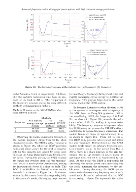
Figure 18. The frequency response at the EaNam bus. (a) Scenario 3. (b) Scenario 4
under Scenarios 3 and 4, respectively. Addition- to raise the grid frequency during cloud cover and
ally, the system’s restoration time from the mo- rapidly recharging excess energy to stabilize the
ment of the fault is 340 s. The comparison of frequency. This process helps restore the initial
the frequency response on bus 25 using different reserve level of the BESS system.
methods is summarized in Table 4.
In Scenario 4, similar to when the time is 100
Table 4. Response on the 500 kV EaNam when s, the system is interrupted with a capacity of
using different methods 144 MW from the Dong Nai generator. With-
out considering BESS, the frequency of 48.7102
Methods
Hz, as shown in Figure 17b, exceeds the min-
Non-battery The The
Scenarios imum value of 49 Hz, leading to system insta-
energy storage proposed CBEST
system method method bility. The frequency response is improved when
3 48.5538 49.07 49.03 the BESS, using the proposed or CBEST method,
4 48.7102 49.143 49.183 participates in system frequency regulation. The
system frequency drops by approximately 30 s,
Observing the results obtained in Scenario 3, as shown in Figure 18b. From 130 to 165 s,
the system frequency drops from 50 Hz when the BESS fully provides active power and raises
cloud cover occurs. The BESS’s active response is the grid frequency. During this time, the BESS
shown in Figure 19a, where the BESS generates system works under the primary frequency con-
additional active power for the grid to compen- trol activated mode. In the period from 165 to
sate for the capacity loss caused by cloud cover 300 s, there is a sharp increase in the grid fre-
affecting the Xuan Thien-EaSup and Srepok 3 so- quency due to the surplus of active power as
lar farms. During this period, the BESS receives generator unit number 6 is reconnected to the
the signal and switches from the “no transmis- grid. At this point, the BESS is responsible for
sion” state to active power transmission, raising absorbing the excess power and smoothing out
the frequency for about 30 s after the fault. The the peak, returning the frequency to the sta-
SOC of the BESS at the 500 kV EaNam bus for ble state. During this time, the BESS system
Scenario 3 is shown in Figure 19b. It demon- works under the secondary frequency control acti-
strates flexible reserve levels that respond quickly vated mode. It can be understood that the SOC
to the system’s needs, discharging deep reserves is recovering. Figure 20a represents the active
643