
Page 120 - IJOCTA-15-4
P. 120
Zhang et al. / IJOCTA, Vol.15, No.4, pp.649-669 (2025)
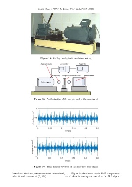
Figure 14. Rolling bearing fault simulation test rig
Figure 15. An illustration of the test rig used in the experiment
Figure 16. Time-domain waveform of the inner race fault signal
iterations, the ideal parameters were determined, Figure 18 demonstrates the IMF components
with K and α values of (5, 550). 662 and their frequency spectra after the IRF signal