
Page 119 - IJOCTA-15-4
P. 119
Rolling bearing fault diagnosis method based on GJO–VMD, multiscale fuzzy entropy, and GSABO–BP...
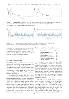
Figure 12. Comprehensive evaluation factors of each intrinsic mode function (IMF) component obtained by
empirical mode decomposition (A) and ensemble empirical mode decomposition (B) methods
Abbreviation: CDF: Comprehensive discriminant factor.
Figure 13. Envelope spectrum of the sensitive IMF1 component obtained from empirical mode
decomposition (A) and ensemble empirical mode decomposition (B) methods
Combined with the comprehensive evaluation fac- Table 2. Specifications of the rolling bearing
tor method, it effectively selects the IMF com-
ponents that are sensitive to signal features, en- Parameter Value
suring accurate identification between signals of Rolling diameter (mm) 8
different states for subsequent analysis. Pitch diameter (mm) 39
Inner diameter (mm) 25
External diameter (mm) 52
Number of rolling elements 9
◦
Contact angle ( ) 0
5. Experimental study
A randomly selected inner race fault (IRF)
The rolling bearing signal used in the experiment
signal is presented in Figure 16. This signal
was selected from the bearing dataset supplied by
Case Western Reserve University. Data were col- exhibits a significant level of noise interference,
lected from the vibration test rig, primarily com- which can be attributed to the absence of a noise-
posed of a three-phase induction motor, coupler, filtering mechanism in the data acquisition equip-
accelerometer, encoder, power meter, and other ment. If the features extracted from this noisy
equipment (Figure 14). Figure 15 illustrates an signal are used directly, it becomes difficult to ac-
overview of the test rig. curately diagnose the rolling bearing’s operating
condition and fault type. Therefore, noise filter-
A 6205 2RSJEM bearing (SKF Group, Swe- ing of the recorded vibration signal is essential to
den) was used in the experiment, with the bearing enhance its features.
specifications presented in Table 2. At a motor
speed of 1797 rpm and a sampling frequency of The IRF signal in Figure 16 was decomposed
12 kHz, the acceleration signal from the bearing using the VMD approach. Prior to decomposi-
at the drive end was recorded. To replicate lo- tion, optimization of α and K was required. Using
calized single-point flaws, electrical spark erosion 10 iterations and a population size of 50, the GJO
was used to form pits on the test bearing’s inner parameter optimization approach was applied. K
ring, outer ring, and rolling elements, measuring and α have search spaces that fall between [100,
0.18 mm in diameter and 0.28 mm in depth. Sixty 5000] and [2, 7], respectively. Figure 17 presents
samples, each containing 3000 data points, were the search results. The fitness value steadily de-
gathered for every fault state. clines as the number of iterations rises. After two
661