
Page 21 - IJOCTA-15-4
P. 21
Control strategies and power converter topologies for switched reluctance motors in electric...
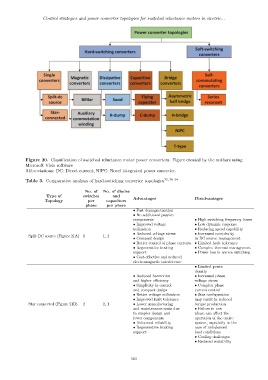
Figure 20. Classification of switched reluctance motor power converters. Figure created by the authors using
Microsoft Visio software
Abbreviations: DC: Direct current; NIPC: Novel integrated power converter.
Table 3. Comparative analysis of hard-switching converter topologies 75,78–94
No. of No. of diodes
Type of switches and
Topology per capacitors Advantages Disadvantages
phase per phase
• Fast demagnetization
• No additional passive
components • High switching frequency losses
• Improved voltage • Low dynamic response
utilization • Reducing speed capability
• Reduced voltage stress • Increased complexity
Split DC source (Figure 21A) 1 1, 2
• Compact design in DC source management
• Better control of phase currents • Limited fault tolerance
• Regenerative braking • Complex thermal management
support • Power loss in source switching
• Cost-effective and reduced
electromagnetic interference
• Limited power
density
• Reduced harmonics • Increased phase
and higher efficiency voltage stress
• Simplicity in control • Complex phase
and compact design current control
• Better voltage utilization • Star configuration
• Improved fault tolerance may result in reduced
Star connected (Figure 21B) 2 2, 1 • Lower manufacturing torque production
and maintenance costs due • Failure in one
to simpler design and phase can affect the
fewer components operation of the entire
• Enhanced reliability system, especially in the
• Regenerative braking case of unbalanced
support load conditions
• Cooling challenges
• Reduced scalability
563