
Page 87 - IJOCTA-15-4
P. 87
Advanced frequency control strategy for power systems with high renewable energy penetration
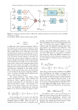
Figure 2. Frequency response method of the power system considering the fluctuation of the renewable
energy source power
Abbreviation: BEES: Battery energy storage system.
supplies, potentially damaging equipment, caus-
∆P ing interruptions, and even resulting in power out-
∆f = − (2)
2HS ages. To mitigate the impact of RESs, it is es-
in which ∆f is the frequency deviation, which is sential to find technological solutions that main-
the change in the power system’s frequency when tain stability and enhance grid reliability. The
there is a change in power, ∆P is the power devi- BESS device offers an ideal solution. It can store
ation, which refers to the difference between the excess energy from RESs and supply it to the
generated power and the consumed power, includ- grid when RES power is low, helping to stabilize
ing changes in power from wind and solar sources, grid frequency. When the BESS is connected to
H is the system inertia constant, a quantity that the power grid, the grid frequency response from
reflects the power system’s ability to resist fre- the rotor dynamic equation is given as follows in
quency changes, depending on the characteristics Equation (4):
of the generators and loads, and S is the system’s
rated power, which is the maximum stable power df s f ref
= P
that the power system can supply. This equation dt H BESS + 2 H
illustrates the relationship between power changes X X X ! (4)
n
and frequency variations in the power system. × P BESS + P G i − P L + P wind +PV
When the generated power and consumed power i=1
are not balanced, the system frequency will fluc- where H BESS is the inertial constant of the BESS
tuate. A system with high inertia will be better that demonstrates the ability to respond when
able to resist frequency changes. controlling the frequency. When the BESS is ap-
The system frequency must always remain plied to provide inertial support during frequency
within the allowable range under varying load fluctuations, its required reference power is ad-
conditions, which requires generators to tem- justed according to the system’s response capac-
porarily compensate for any deviation by using ity. It can be evaluated as given in Equation (5), 29
ref 0
ref 1
their stored kinetic energy. The frequency re- in which P BESS and P BESS are the reference pow-
sponse of the power system from the governor ers with and without controlling the frequency,
of the ith generator, considering the connected respectively.
28
RESs, can be defined as follows in Equation (3) :
P ref 1 = P ref 0 H BESS f s df s (5)
! BESS BESS dt
n
df s f ref X X X
= P P G i − P L + P wind +PV (3) The BESS is used to store excess energy from
dt 2 H
i=1 RESs and release this energy when needed to re-
From Equation (3), it can be seen that the duce the frequency fluctuations. However, the
grid frequency will fluctuate due to the constantly performance of the BESS depends on the control
changing output of RESs. This can lead to an strategy. The detailed model and controller of the
unstable electrical system due to irregular power BESS are discussed in the next section.
629