
Page 88 - IJOCTA-15-4
P. 88
Viet Thanh et al. / IJOCTA, Vol.15, No.4, pp.625-648 (2025)
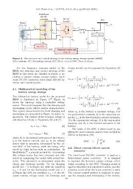
Figure 3. The structure and control strategy of the battery energy storage system (BEES)
Abbreviations: AC: Alternating current; DC: Direct current; SOC: State-of-charge.
For the frequency response model of the charge models can be expressed by Equations (8)
BESS, the structure and control strategy of the and
BESS in this study are detailed in Figure 3, in-
cluding a battery energy storage system, buck- Q
boost DC/DC converter, three-phase AD/AC in- u oc ch = u 0 − k R i b dt + 0.1Q i l f
verter, and control system. Z
Q R i b dt)
− k R i b dt + Ae (−B
Q − i b dt
2.1. Mathematical modeling of the
(8)
battery energy storage
The lithium-ion battery model for the proposed u oc disch = u 0 − k Q
BESS is illustrated in Figure 4. 30 Figure 4a Q − R i b dt i l f
shows the topology using a controlled voltage Q Z R
− k i b dt + Ae (−B i b dt)
source. This model assumes that the charging and Q − R i b dt
discharging cycles exhibit similar characteristics. (9)
The typical characteristics for both charging and where u 0 is the battery a constant voltage, k is
discharging are presented in Figure 4b and c, re- the polarization constant, Q is the maximum ca-
spectively. The output of the terminal voltage is pacity, i l f is the low-frequency current dynamics,
calculated as follows in Equations (6) and (7). A is the exponential voltage, B is the exponential
capacity, and R b is the internal resistance of the
(6) battery.
u b = u ch − R b i b
The value of the SOC is determined by ap-
plying the most common ampere-hour method as
u b = u disch − R b i b (7)
follows in Equation (10).
where R b is the internal resistance of the battery,
Z
i b is the battery current, and u oc is the voltage SOC = 1 − i b t dt (10)
source that is primarily determined by the ac- Q
tual SOC of the battery, while also being influ-
2.2. Direct current/direct current
enced by other factors such as polarization. In converter
MathWorks, 30 a general method for determining
this voltage source has been proposed and vali- The buck-boost DC/DC converter is used as a
dated by comparing the model with actual bat- bidirectional power converter. It is designed
teries. The calculation is determined under the to regulate the battery’s output voltage, which
charge and discharge models. For the charging varies according to the SOC. Charging power is
model (sel = 1 in Figure 4a) with the condition applied when the buck converter is active, and dis-
i l f < 0 and for the discharging model (sel = 1 charging occurs when the boost converter is used.
in Figure 4a) with the condition i l f < 0, the ob- The current control method is employed to man-
tained battery voltage under the discharge and age the charging and discharging of the battery.
630