
Page 91 - IJOCTA-15-4
P. 91
Advanced frequency control strategy for power systems with high renewable energy penetration
in which f ofs,max and f ofs,min are the maxi- control after abnormal voltage fluctuations oc-
mum and minimum offset frequencies, respec- cur. The amount of reactive power injected or
tively. SOC tot is the SOC control range, and K r absorbed by the BESS device in response to a
is the primary droop gain and can be expressed given voltage change must comply with grid code
as follows in Equation (17): requirements. The reference reactive power con-
trol signal is generated based on the voltage er-
ror between the voltage at PCC and the refer-
ence voltage, following the droop control method.
1
K r = K A K f ∆f · − P ref · 1 In this study, the droop control method was ap-
K f (17)
K E s plied from the perspective of the Australian En-
| {z }
| {z }
∆SOC
∆SOC ref ergy Market Operator (AEMO), and the droop
characteristic of voltage variation corresponding
= |∆f − f of (s)| K A
to reactive power is shown in Figure 6. The refer-
where K A is the amplifier gain and f ofs is the offset ence reactive power control signal can be obtained
frequency. In this study, for the reference point as follows in Equation (19):
corresponding to the frequency is 50 Hz and the
BESS power is zero, the offset frequency used for 1
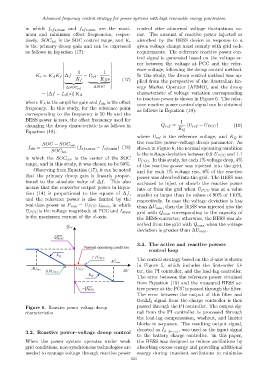
changing the droop characteristic is as follows in Q ref = (U ref − U PCC ) (19)
K Q
Equation (18).
where U ref is the reference voltage, and K Q is
the reactive power–voltage droop parameter. As
SOC − SOC cen
f ofs = (f ofs,max − f ofs,min ) (18) shown in Figure 6, the normal operating condition
SOC tot
is the voltage deviation between 0.9 U PCC and 1.1
in which the SOC cen is the center of the SOC
U PCC . In this study, for each 1% voltage drop, 4%
range, and in this study, it was chosen to be 50%.
of the reactive power was injected into the grid,
Observing from Equation (17), it can be noted and for each 1% voltage rise, 6% of the reactive
that the primary droop gain is linearly propor- power was absorbed into the grid. The BESS was
tional to the absolute value of ∆f. This also activated to inject or absorb the reactive power
means that the converter output power in Equa- into or from the grid when U PCC was at a value
tion (14) is proportional to the square of ∆f,
smaller or larger than its values of 90% or 110%,
and the reference power is also limited by the
respectively. In case the voltage deviation is less
real-time power as P max = U PCC I dmax , in which
than ∆U min , then the BESS was injected into the
grid with Q max corresponding to the capacity of
U PCC is the voltage magnitude at PCC and I dmax
is the maximum current of the d-axis. the BESS-converter; otherwise, the BESS was ab-
sorbed from the grid with Q max when the voltage
deviation is greater than ∆U max .
3.3. The active and reactive powers
control loop
The control strategy based on the d-axis is shown
in Figure 5, which includes the first-order fil-
ter, the PI controller, and the lead-lag controller.
The error between the reference power obtained
from Equation (15) and the measured BESS ac-
tive power at the PCC is passed through the filter.
The error between the output of this filter and
the∆I d signal from the charge controller is then
Figure 6. Reactive power–voltage droop passed through the PI controller. The output sig-
characteristics nal from the PI controller is processed through
the lead-lag compensation, washout, and limiter
blocks in sequence. The resulting output signal,
, was used as the input signal
denoted as I d −p −ref
3.2. Reactive power–voltage droop control
to the battery charge controller. In this paper,
When the power system operates under weak the BESS was designed to reduce oscillations by
grid conditions, non-synchronous technologies are absorbing excess energy and providing additional
needed to manage voltage through reactive power energy during transient oscillations to minimize
633