
Page 89 - IJOCTA-15-4
P. 89
Advanced frequency control strategy for power systems with high renewable energy penetration
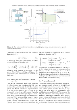
Figure 4. The battery model. (a) Equivalent model, (b) typical charge characteristics, and (c) typical
discharge characteristics.
The injected power to the DC-link is as follows in DC/AC converter to the grid can be obtained as
32
31
Equation (11) : follows in Equation (13) :
2
(11) U
P b = m b U dc I b P BESS = U BESS U P CC cos δ − P CC cos θ g
Z f Z f
in which, m b is the duty cycle and can be deter- + U BESS U P CC sin δ sin θ f
Z f (13)
mined as follows in Equation (12). U 2
Q BESS = U BESS U P CC cos δ − P CC sin θ g
Z f Z f
U BESS U P CC
− sin δ cos θ f
∗ Z ∗ Z f
P P
b b
m b = K p b − I b + K i b − I b dt (12)
where U BESS is the output voltage of VSC, U PCC
U b U b
is the voltage at the point of common coupling
∗
where P is the reference value injected into the
b (PCC), δ is the power angle, Z f is the filter
power of the DC-link, and K p b and K i b are the
impedance and is defined as Z f = R f +jX f , θ g
proportional gain and integral time constant, re- is the impedance angle, R f is the filter resistance,
spectively. and X f is the filter reactance and is considered
based on the filter inductance L f .
2.3. Direct current/alternating current
converter 3. Proposed control
The DC/AC converter is used in the BESS to To enhance the frequency stability of the system,
interface between the buck-boost DC/DC con- the converter control strategy for the BESS was
verter and the grid through the AC filter. In this considered in this work, as shown in Figure 5.
paper, the DC/AC converter is implemented as This control system provided the voltage mag-
a voltage source converter (VSC), which gener- nitude and phase set points to generate a sinu-
ates an AC voltage from a DC source. Typically, soidal reference signal for the PWM scheme of the
the VSC uses six insulated-gate bipolar transis- DC/AC converter. The voltage magnitude and
tors, which operate based on pulse-width mod- phase set points were determined using the ref-
ulation (PWM) with switching control. These erence voltage and frequency, which were derived
insulated-gate bipolar transistors are usually con- through the outer and inner control loops. For
trolled through PWM to regulate power flow. frequency stability, the BESS was used to support
The active and reactive power delivered from the active power. Therefore, the d-axis reference was
631