
Page 101 - MSAM-3-2
P. 101
Materials Science in Additive Manufacturing NiTi lattice: Performance optimization
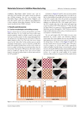
conditions. HyperMesh (2019 version) was used to As shown in (Figure 2C and D), there are more powder
mesh the I-WP, and the I-WP lattice model was divided particles adherent to the underside than to the side. It can
into 1387668 elements. The BCC was optimized using also be observed that the powder adhesion was more severe
Materialise Magics software (Materialise, Belgium), and at the BCC sample node, where the powders accumulated
then, the volume mesh was re-divided using Materialise at the nodes. Despite the larger cantilever area, less powder
3-Matic software (Materialise, Belgium). The BCC lattice adhesion was observed at the I-WP sample node than at
model was divided into 230681 elements. the BCC sample node, due to the better self-supporting
properties of the I-WP TPMS structure. 34,35 Thus, the unit
3. Results and discussion cell type of lattice structures is an important factor affecting
3.1. Surface morphologies and molding accuracy fabrication quality. Although the I-WP TPMS is not spared
from powder adhesion on the surface of the lower side, it is
Figure 2 shows that the surfaces of both BCC and I-WP still superior to the BCC lattice.
lattice structures are very rough and covered with many
powder particles, which is usually caused by the partial The size and weight of the NiTi lattice structure were
melting of nearby powder by the energy dissipated from measured by vernier caliper and electronic balance,
the molten pool. By observing the side surface of the two respectively. The actual volume fraction was calculated by
lattice structure pillars from the side view, some stripes determining the ratio of the actual mass of the sample to
caused by the “stair effect” of the addition process can be the design mass. As shown in the (Figure 2E and F), the
observed. Furthermore, it can be observed in both BCC average actual volume fractions of BCC and I-WP lattice
and I-WP samples that the lower surface of the node and structure samples are 12.26% and 12.30%, respectively,
strut is rougher and has more attached particles than the which are higher than the design volume fraction. This is
side surface. During the LPBF process, the node locations because, during the LPBF process, many powder particles
acted as cantilevers, and the lower side surfaces lacked are attached to the sample surface, especially at the lower
support, causing the surface there to adhere more easily to surface. As a result, the actual quality of the sample
the NiTi powder. 31-33 increases, followed by an enlargement of the actual volume
A C
B D
E F
Figure 2. (A-F) Scanning electron microscope images and actual volume fraction of as-built lattices.
Volume 3 Issue 2 (2024) 4 doi: 10.36922/msam.3380