
Page 105 - MSAM-3-4
P. 105
Materials Science in Additive Manufacturing Bistable 3D-printed compliant structure
A C
B
D
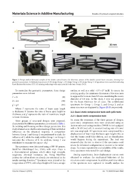
Figure 2. Design and as-fabricated samples of the double curved beams (A) Schematic picture of the double curved beam structure, showing four
geometric parameters. As-fabricated specimens of: (B) design Group 1, (C) design Group 2, (D) design Group 3. All specimens were manufactured using
fused filament fabrication (FFF) 3D printing technology with onyx material. Scale bars: 30 mm (B-D).
To normalize the geometric parameters, three design outline, as well as a solid −45°/+45° infill. To ensure the
parameters were defined: printing quality, the minimum dimension of the structures
l’ = l/t (II) is supposed to be more than 0.8 mm considering the nozzle
diameter of 0.4 mm. In this study, 1 mm was proposed
h’ = h/t (III) for the beam thickness for all cases. The as-fabricated
g’ = g/t (IV) specimens for Group 1, Group 2, and Group 3, and an
array structure are displayed in Figure 2B-D, respectively.
Where l’ represents the ratio of beam span length
to thickness; h’ denotes the ratio of beam apex height to 2.2. Quasi-static compression tests and cyclic tests
thickness; and g’ represents the ratio of membrane length
to beam thickness. 2.2.1. Quasi-static compression tests
Three groups of structural designs were proposed, To assess the responses of the three groups of designs,
characterized by different parameters, as outlined in Table 1. quasi-static compression tests were conducted using an
By isolating and focusing on three design parameters, this Instron universal testing machine (5900R Series) equipped
study attained an in-depth understanding of their individual with a 30 kN load cell. A constant loading rate of 6 mm/
influences on the structural response. A comparison min was employed. All specimens were compressed by a
between Group 1 and Group 2 was performed to study the displacement of four times the beam apex height (4h), so
influence of l’, while the study within Group 1 or Group 2 that the beams could fully deform, and no densification
indicated the influence of h’. In addition, Group 3 was would happen during the experiment. The load was
established to examine the impact of g’. removed after the test to observe if the specimens could
retain the deformed configuration or recover to the initial
The specimens were fabricated using a FFF 3D printer, shape. To ensure repeatability and reliability of the results,
MarkTwo (Markforged Inc., USA), with onyx. Onyx is three specimens were tested for each design.
a fiber-reinforced polymer, which offers high strength,
toughness, chemical resistance, etc. Using MarkTwo During experiments, force-displacement curves were
printer, the carbon fibers are already pre-orientated in the obtained to evaluate the mechanical behaviors of the
nozzle-moving direction. Specimens were printed at the structures under compression. In addition, real-time videos
37
temperature of 275°C, with a layer height of 0.1 mm, a single of the specimens were captured to visually analyze the
Volume 3 Issue 4 (2024) 4 doi: 10.36922/msam.4960