
Page 106 - MSAM-3-4
P. 106
Materials Science in Additive Manufacturing Bistable 3D-printed compliant structure
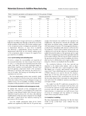
Table 1. Geometric parameters and design parameters for three groups of designs
Group No. of design Geometric parameters Design parameters
t (mm) h (mm) l (mm) g (mm) h' l' g'
Group 1: l' = 30 No. 1 1 3 30 1 3 30 1
g' = 1 No. 2 1 4 30 1 4 30 1
No. 3 1 5 30 1 5 30 1
Group 2: l’ = 60 No. 4 1 3 60 1 3 60 1
g’ = 1 No. 5 1 4 60 1 4 60 1
No. 6 1 5 60 1 5 60 1
Group 3: l’ = 60 No. 6 1 5 60 1 5 60 1
h' = 5 No. 7 1 5 60 3 5 60 3
No. 8 1 5 60 5 5 60 5
responses of different designs and observe any distinctive samples, their behavior was modeled by two rigid plates for
behaviors regarding snap-through. It should be noted that simplification. The interaction between the specimen and
all the specimens were tested with bottom surfaces taped rigid plates was defined using a normal contact behavior
to the compression plate to mitigate any potential sliding with hard contact formulation. For the tangential behavior, a
or detachment. Moreover, in cases where bi-stability penalty friction formulation with a friction coefficient of 0.3
was observed, a supplementary testing procedure was was employed. A plane strain condition was assumed, with
37
implemented with both top and bottom surfaces glued a thickness of 12 mm in the z-direction. Tie interaction was
to the compression plates to measure the negative force applied between the surfaces of the specimen and two rigid
generated from bi-stability. plates. The corresponding surfaces of the rigid plates were set
as the master surfaces, while the top and bottom surfaces of
2.2.2. Cyclic loading and unloading tests the specimen were the slave surfaces. In addition, the bottom
To further evaluate the recoverability and reusability of plate was fixed in all directions, and a negative displacement
the proposed structures, the three designs from Group 2 along the y-direction was deployed onto the top plate.
(l’ = 60, g’ = 1) were selected as representatives to be tested The constitutive behavior of the base material was
under cyclic load. The tests were conducted using the simplified to be elastic-perfect plastic, with an elastic
same Instron machine mentioned earlier. The cyclic tests modulus of 1800 MPa and a yield strength of 61 MPa.
involved applying compression loads to the specimens, The density was 1.2 g/cm , and Poisson’s ratio was 0.3,
3
followed by unloading and repeating the process for a respectively. Four-node bilinear plane strain quadrilateral
38
total of 30 cycles. The loading and unloading rates were (CPE4R) elements were used to discrete the structure.
maintained at 6 mm/min. Mesh sizes of 0.25 mm and 0.4 mm were selected to
The force-displacement curves were recorded, which capture the response of the curved beam and the rest of
then were converted to effective stress-strain curves. Based the structure, respectively, to minimize the computational
on the observations of the peak loads, dissipated energy, and cost and ensure the simulation accuracy according to a
residual strains, the recoverability, reusability, and energy convergence study.
dissipation of the proposed structures could be assessed. The results from the FE model were compared to the
2.3. Numerical simulation and convergence study experimental results. The validated model was then used
to simulate the responses of single-beam and triple-beam
To analyze the responses of the metamaterials under structures with the same relative density as the double-
quasi-static compression, a finite element (FE) model was beam structure. A comparison was made between these
developed using Abaqus/Explicit 2020 (Dassault Systems structures to investigate how the number of coupling
SIMULIA Corp, Providence, RI, US). Due to the relatively beams affects compliant behavior further.
small thickness of the specimens compared to their height
and width, a simplification was made by modeling the 2.4. Analytical modeling
specimens as 2D structures. The force-displacement relationships for the first three
Since the metallic compression plates of the Instron modes of the curved beam under vertical force are
machine were significantly stiffer than the 3D-printed onyx expressed as: 24
Volume 3 Issue 4 (2024) 5 doi: 10.36922/msam.4960