
Page 75 - MSAM-3-4
P. 75
Materials Science in Additive Manufacturing Impact resistance and porous structures
of the structure after impact deformation were analyzed Table 1. Structural parameters of uniform triply periodic
using super depth-of-field microscopy. The findings of this minimal surface structures
study will offer design guidelines and performance insights Specimen Cell size (mm) Porosity (%)
for gradient gyroid energy-absorbing structures.
G-E2 2 70.65
2. Methods G-E2.5 2.5 76.09
2.1. TPMS porous structure design G-E3 3 79.87
G-E3.5 3.5 82.64
Gyroid TPMS structures were designed using MATLAB
code (Equation I): G-E4 4 84.74
2 xπ 2 yπ 2 yπ Table 2. Structural parameters of graded gyroid structures
F gyroid = sin × cos + sin
s s s Specimen Element size (mm) Porosity (%) Function
2 z π 2 z π 2 x π G-Linear I 2 (top)→4 (bottom) 73 Linear:
× cos + sin × cos (I) 1
s s s G-Linear II 4 (top)→2 (bottom) s = z + 2
6
where s denotes the unit cell size, and t(x,y,z) represents G-Quadratic I 2 (top)→4 (bottom) 73 Quadratic:
the relative density variation parameter controlling the G- Quadratic II 4 (top)→2 (bottom) s = z 2 + 2
structure of minimal surfaces. The minimum surface was 72
obtained when the generation function of gyroid structure G-Sine I 2 (top)→4 (bottom) 73 Sine:
(F gyroid ) in Equation I is equal to zero, that is, its mean G-Sine II 4 (top)→2 (bottom) s =+ ( π z )
3 sin
curvature is zero, and the surface has no self-intersections. 12
The parameter s (unit cell size) in Equation I controls the Note: Arrows indicate the trend of the element's size.
unit cell size, and the number of gyroid layers is adjusted
within the range of (x, y, z). As listed in Table 1, this work
involved five gyroid structures with different cell sizes, that
is, G-E2, G-E2.5, G-E3, G-E3.5, and G-E4; their design
models are displayed in Figure 1.
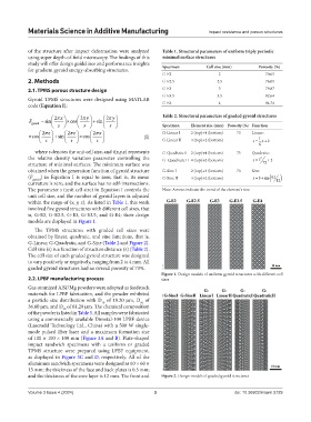
The TPMS structures with graded cell sizes were
obtained by linear, quadratic, and sine functions, that is,
G-Linear, G-Quadratic, and G-Sine (Table 2 and Figure 2).
Cell size (s) is a function of structure distance (z) (Table 2).
The cell size of each graded gyroid structure was designed
to vary positively or negatively, ranging from 2 to 4 mm. All
graded gyroid structures had an overall porosity of 73%.
Figure 1. Design models of uniform gyroid structures with different cell
2.2. LPBF manufacturing process sizes
Gas-atomized AlSi7Mg powders were adopted as feedstock
materials for LPBF fabrication, and the powder exhibited
a particle size distribution with D of 19.20 μm, D of
10
50
36.60 μm, and D of 61.20 μm. The chemical composition
90
of the powder is listed in Table 3. All samples were fabricated
using a commercially available Dimetal-100 LPBF device
(Laseradd Technology Ltd., China) with a 500 W single-
mode pulsed fiber laser and a maximum formation size
of 100 × 100 × 100 mm (Figure 3A and B). Plate-shaped
impact sandwich specimens with a uniform or graded
TPMS structure were prepared using LPBF equipment,
as displayed in Figure 3C and D, respectively. All of the
aluminum sandwich specimens were designed as 60 × 60 ×
13 mm; the thickness of the face and back plates is 0.5 mm;
and the thickness of the core layer is 12 mm. The front and Figure 2. Design models of graded gyroid structures
Volume 3 Issue 4 (2024) 3 doi: 10.36922/msam.5729