
Page 76 - MSAM-3-4
P. 76
Materials Science in Additive Manufacturing Impact resistance and porous structures
back contact surfaces are non-porous solids. A total of five recorded, and the corresponding EA values were obtained
uniform TPMS structures and six graded TPMS structures according to Equation II.
were printed. The process parameters were optimized to d
improve the dimensional accuracy of the LPBF-formed EA = ∫ 0 F ()x dx (II)
lattice structure, and the optimized process parameters are
listed in Table 4. After the impact test was completed, the samples were
removed, and their 3D morphology was observed using an
2.3. Morphology and impact resistance ultra-deep field microscope (VHX-5000; KEYENCE Co.,
characterization Ltd., Japan). The diameter and depth of the indentation
Various sandwich TPMS structure samples were impacted were measured accordingly (Figure 5).
using a drop hammer impact tester (STLH-1000; Jinan 3. Results and discussion
Shangtai Testing Instrument Co., China) at impact
velocities of 7 and 10 m/s, respectively (Figure 4). The 3.1. Impact resistance of uniform TPMS sandwich
plate sandwich samples were placed flat on the test bench, structures
and the impact site was aimed at the center of the sample. Figures 6A and B display the force-displacement curves
The load (F(x)), time (t), and displacement (d) of each of the uniform TPMS sandwich structure for impact
sandwich structure sample during the impact test were response velocities of 7 and 10 m/s, respectively. Here, the
initial starting point for calculating the displacement is the
Table 3. Chemical composition of the AlSi7Mg powder
impact surface (i.e., the front contact layer). The impact
Elements Al Si Mg Zn Cu Ni O Fe Ti Mn force trends of the uniform TPMS sandwich structures
Content Bal. 7.01 0.56 0.015 0.01 0.01 0.036 0.073 0.15 0.01 with different cell sizes are consistent, indicating that the
(wt.%) fabricated samples are of good quality. At an impact velocity
Abbreviation: Bal.: Balance. of 7 m/s, the impact force displays an increasing and then
decreasing trend with increasing displacement. Notably,
Table 4. Processing parameters for the laser powder bed the variation interval of the impact force increases with
fusion (LPBF)‑fabricated AlSi7Mg porous structures increasing cell size, that is, the buffer distance increases.
The dimension of the sandwich TPMS structure along the
Process parameters Value impact direction was 13 mm, and the results indicated
Laser power (W) 220 that the displacement relative to the impact surface was
Scanning speed (mm/s) 1200 <13 mm when the cell size was <3 mm.
Hatching space (mm) 0.09 When the impact velocity was increased to 10 m/s, the
Layer thickness (mm) 0.03 impact force of the sandwich TPMS structure with small cell
A B
C
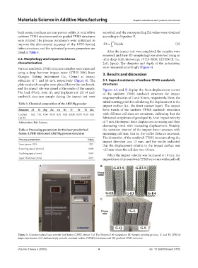
Figure 3. Commercialized laser powder bed fusion (LPBF) device. (A) The Dimetal-100 equipment. (B) Sample printing process. (C and D) LPBFed
impact specimens: (C) Uniform triply periodic minimal surface (TPMS) structures; and (D) gradient TPMS structure
Volume 3 Issue 4 (2024) 4 doi: 10.36922/msam.5729