
Page 68 - MSAM-4-1
P. 68
Materials Science in Additive Manufacturing In situ electromagnetic field manipulation during LMD
A D
B E
C F
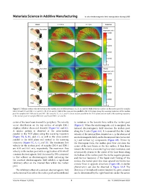
Figure 5. Different surface velocity vectors in the molten pool at different times. (A, D, a1, and d1) Half of the top surface on the molten pool for samples
EM-0 (A and D) and EM-1 (a1 and d1). (B, E, b1, and e1) Half of the cross-section parallel to the YOZ plane along the scanning trajectory of the molten
pool for samples EM-0 (B and E) and EM-1 (b1 and e1). (C, F, c1, and f1) Cross-section parallel to the XOZ plane and vertical to the scanning trajectory
of the molten pool for samples EM-0 (C and F) and EM-1 (c1 and f1)
center of the laser beam toward the periphery. The velocity to variations in the Lorentz force within the molten pool
vector distribution on the top surface of sample EM-1 (Figure 6). When the electromagnetic coil is energized, the
displays relative chaos and disorder (Figure 5a1 and d1). induced electromagnetic field traverses the molten pool
A similar pattern is observed at the cross-section along the Z-axis (Figure 6A). It is assumed that the initial
parallel to the YOZ plane along the scanning trajectory velocity of the internal flow, denoted as v, in the absence of
(Figure 5B, E, b1, and e1), as well as the cross-section an electromagnetic field, can be decomposed into horizontal
parallel to the XOZ plane and vertical to the scanning (v ) and vertical (v ) components (Figure 6B). Driven by
1
2
trajectory (Figure 5C, F, c1, and f1). The maximum flow the Marangoni force, the molten pool flow circulates the
velocity in the molten pool of samples EM-0 and EM-1 center of the laser beam on the free surface. It then flows
are 0.58 and 0.41 m/s, respectively. The maximum flow toward the bottom, encountering boundary resistance, and
velocity in the molten pool with an application of 39.40 mT subsequently returns to the center of the laser beam along
constant electromagnetic field decreases by 29% compared the bottom of the molten pool. Due to the negative pressure
to that without an electromagnetic field, indicating that and thermal buoyancy of the liquid melt flowing off the
the constant electromagnetic field exhibits a significant surface, the molten pool flow rises upward and forms two
inhibitory effect on the internal flow within the molten circular flows in opposite directions (Figure 6B). A similar
pool. phenomenon can also be observed in Figure 5A-F. The
The inhibitory effect of a constant electromagnetic field direction of the induced current (marked by green crosses)
on the internal flow within the molten pool can be attributed can be determined by the right-hand rule under the action
Volume 4 Issue 1 (2025) 9 doi: 10.36922/msam.8332