
Page 128 - MSAM-4-3
P. 128
Materials Science in Additive Manufacturing 3D-Printed hip joints performance
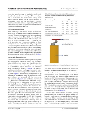
properties, including ease of synthesis, good tensile Table 1. Mechanical properties of dental photopolymer
strength, adequate biocompatibility, and low toxicity, as resin with varying concentration of TiO nanoparticle
2
well as antibacterial and photocatalytic activity. These reinforcement
nanoparticles are widely used as catalyst supports in Mechanical properties Value
biomedicine, water and air purification, pigments, 0% 1% 3% 5%
cosmetics, solar cells, and tissue engineering. 12,13 The TiO TiO TiO TiO TiO
2
nanoparticles used in this study were nanoparticles with an Density (g/cm3) 1.13 2 1.15 2 1.19 2 1.20 2
average particle diameter of 10 nm.
Young’s modulus (MPa) 201 232 317 365
2.3. Numerical simulation Poisson’s ratio 0.43 0.43 0.43 0.43
Before conducting a finite element analysis, the mechanical Yield tensile strength (MPa) 17.99 22.80 28.29 21.62
properties of the material were determined for simulation Ultimate tensile strength (MPa) 38.44 40.32 43.90 34.83
purposes. These properties were derived from experimental Abbreviation: TiO : Titanium dioxide.
2
engineering stress–strain data, which were subsequently
converted into actual stress–strain data and input into
the finite element analysis software. The material used
in the simulation was a composite consisting of dental
photopolymer resin reinforced with TiO nanoparticles.
2
The engineering stress–strain behavior of this composite has
been previously characterized. Curve fitting was performed
based on the experimental engineering stress–strain graph
data, and the fitting process was refined until an R value of
2
≥0.95 was achieved. The resulting mechanical properties of
the composites obtained from the study are shown in Table 1.
2.4. Sample characterization
The mechanical properties of TiO nanoparticle composites
2
were validated by conducting tensile test simulations
using ANSYS software (Ansys, Inc., United States). The
simulations were performed on specimens conforming Figure 5. Schematic illustration of the artificial hip joint compression test
to ASTM D638-14 type V standards. The dimensions
of the specimens are shown in Figure 6. The boundary This setting was also used in the simulation process, with
conditions applied were fixed support on side A and a boundary conditions set according to the ISO standard.
velocity of 1 mm/min moving upward parallel to the Y-axis
on side B (Figure 7). The tensile test simulation was set up A finite element study simulates the compression test
following the experimental setup. The results of the tensile to be performed on the artificial hip joint. Finite element
test simulation were compared with the experimental simulation testing was performed using Ansys software
test, as shown in Figure 8. The mechanical properties of based on the ISO 7206-6 test standard. This standard provides
TiO nanoparticle composites were considered valid if information on the placement position of the artificial hip
2
the difference or error between the two tests was ≤5%. joint, including both the depth and angle of installation of
11
This standard was also applied to the simulation process the artificial hip joint to the bracket. According to the ISO
to validate consistency between the experiment and 7206-6 standard, the angle of installation of the artificial hip
simulation. The tensile test sample was fabricated using the joint must be α = 10° and β = 9°, with a depth of installation
same 3D printing tool as the fabrication of compression to the bracket as in the real case of total or partial hip joint
test samples, as explained in the methodology section. replacement, as shown in Figure 9A.
We used a speed of 1 mm/min and provided details of To shorten the simulation time, the bracket geometry
the specimen dimensions in tensile testing. While in was excluded from the simulation process. Instead, the
compression testing, we applied the ISO 7206-6 standard. boundary conditions were set, namely, the femoral stem
This standard provides information on the position of section was defined as a fixed support following the ISO
the artificial hip joint placement, including both the 7206-6 standard. Then, the crosshead geometry that pressed
installation depth and angle of the artificial hip joint to the the artificial hip joint was defined as moving downward
bracket. The compression speed in this test was 2 mm/min. in the Y-axis direction at a speed of 2 mm/min, as shown
Volume 4 Issue 3 (2025) 4 doi: 10.36922/MSAM025200032