
Page 129 - MSAM-4-3
P. 129
Materials Science in Additive Manufacturing 3D-Printed hip joints performance
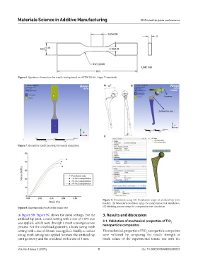
Figure 6. Specimen dimensions for tensile testing based on ASTM D638-14 type V standards
A B
C
Figure 7. Boundary condition setup for tensile simulation
Figure 9. Simulation setup (A) Installation angle of artificial hip joint
bracket. (B) Boundary condition setup for compression test simulation.
Figure 8. Experimental result of the tensile test (C) Meshing process setup for compression test simulation
in Figure 9B. Figure 9C shows the mesh settings. For the 3. Results and discussion
artificial hip joint, a mesh setting with a size of 7.079 mm 3.1. Validation of mechanical properties of TiO
was applied, which went through a mesh convergence test nanoparticle composites 2
process. For the crosshead geometry, a body sizing mesh
setting with a size of 20 mm was applied. Finally, a contact The mechanical properties of TiO nanoparticle composites
2
sizing mesh setting was applied between the artificial hip were validated by comparing the tensile strength at
joint geometry and the crosshead with a size of 3 mm. break values of the experimental tensile test with the
Volume 4 Issue 3 (2025) 5 doi: 10.36922/MSAM025200032