
Page 81 - ARNM-2-3
P. 81
Advances in Radiotherapy
& Nuclear Medicine OrthoCT experimental proof of concept
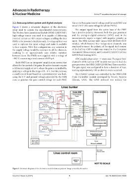
2.2. Data acquisition system and digital analysis The active base gain control voltage used for each PMT was
Figure 5 shows a schematic diagram of the electronic set at 5.30 V (the same voltage for all the PMTs).
setup used to acquire the experimental measurements. The output signal from the active base of the PMT
The Nuclear Instrumentation Module (NIM) CAEN N471 has a positive polarity. However, both the gate generator
high-voltage source was used. It is capable of delivering and the analog-to-digital converter (ADC) used in the
3 mA of current at 3 kV output voltages, enabling the four measurements require a signal with negative polarity as
PMTs to be powered simultaneously. A voltage splitter was input. The NIM LeCroy 428F Linear FAN-IN/FAN-OUT
used to replicate the input voltage and make it available module, which features four independent channels, was
to four outputs. With this configuration, any variation in employed to invert the polarity of the signal. Each output
the supply voltage would be common to all the channels, of the LeCroy 428F module was routed to the Computer
resulting in an approximately zero relative variation Automated Measurement and Control (CAMAC) LeCroy
between them. The PMTs were supplied with a voltage of 2259B Peak Sensing ADC.
−982 V, consuming a total current of 479 µA. ADC module channels 8 – 11 were used. The signal from
Each PMT has an integrated amplification system that channel 4 of the LeCroy 428F module was used to feed the
allows for the control of its gains. Its active elements require gate generator, the NIM CAEN 2255B Dual Timer module.
a differential supply of ±6 V, where the gain is controlled by The gate signal was configured to have a duration of 5 µs,
applying a voltage in the range of 0 – 6 V. For this purpose, starting approximately 100 ns after an event occurred.
a small circuit board based on a potentiometer was built, The CAMAC system was controlled by the 3988 GPIB
using the 6 V and ground voltages provided by the NIM Crate Controller module developed by Kinetic Systems
crate to generate the gain control voltage for each PMT. (Illinois, USA). The GPIB protocol was utilized for
Figure 5. Schematic diagram of the electronics used for data acquisition. Image created by the author.
Volume 2 Issue 3 (2024) 4 doi: 10.36922/arnm.4099