
Page 85 - ARNM-2-3
P. 85
Advances in Radiotherapy
& Nuclear Medicine OrthoCT experimental proof of concept
the phantom and the collimator surface was 80 mm. The 2.5.2. Longitudinal scan along the phantom
phantom was irradiated with a 5 mm × 5 mm beam at To obtain a longitudinal scan, the phantom was moved
the isocenter (as described in section 2.3) with the linac from Z = −60 mm to Z = +60 mm in steps of 10 mm
head positioned at 270° (i.e., the beam entered from the (distances as defined in the experimental setup depicted
left side of the phantom). Each acquisition lasted 45 s to in Figure 11).
acquire at least 1000 events for each phantom position.
This long-time irradiation was due to the dead time of 2.5.3. 2D scan of air cavity region
the acquisition system. However, the aim of this work was A 2D image of the air cavity region was obtained. For this
to demonstrate the concept of the OrthoCT technique. purpose, longitudinal scans were performed at different
Therefore, optimizing the acquisition system, including heights, effectively creating a 2D scan in the region of the
considerations of dead time, was not considered within the air cavity. The longitudinal scans covered an area between
scope of this study. Z = −62 mm and Z = +70 mm with steps of ΔZ = 22.8 mm.
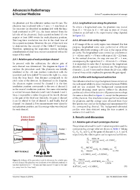
2.5.1. Relative gain of each prototype channel In the vertical direction, the step size was ΔY = 5 mm,
encompassing the region from Y = −30 mm to Y = +30 mm.
To proceed with the calibration, the relative gain of It is important to note that Z represents the longitudinal
each channel was determined. The diagram in Figure 12 direction, while Y expresses the vertical one. The prototype
outlines the procedure used. The phantom was initially channels 1, 2, and 3 were used to obtain the 2D scan, while
irradiated at the −60 mm position (coincident with the channel 4 was solely employed to generate the gate signal.
isocenter) and then shifted 7.6 mm to the right (i.e., away
from the linac head). This distance corresponds to the 2.5.4. Profiles with background subtraction
pitch value of the detector. As illustrated in the diagram, The influence of subtracting a background measurement on
the phantom region covered by channel 1 in the first the technique’s ability to detect variations between PMMA
irradiation position corresponds to the area of channel 2 and air was analyzed. The background measurement
in the second irradiation position. The same relationship involved obtaining count spectra without the phantom
is verified between channels 2 and 3 and channels 3 and 4. positioned in front of the detector. All parameters were kept
Thus, it is possible to relate the gain of the fourth channel the same as described in Figure 11, except for the presence
to the gain of the third one. Similarly, the gain of channel of the phantom. Five irradiations were performed without
2 can be related to that of channel 3, and finally, that of the phantom, and the average value obtained from these
channel 1 to channel 2. Five measurements were taken for five spectra was used as the background measurement for
each phantom position, and the average value was obtained the corresponding channel. The background-subtracted
for each channel. profiles were then obtained using the data acquired in
sections 2.5.2 and 2.5.3.
3. Results and discussion
3.1. Relative gain of each prototype channel
The µ values obtained for each irradiation position and the
corresponding average value are shown in Table 1. Taking
G , G , G , and G as the gains of channels 1, 2, 3, and 4,
1
4
3
2
respectively, the relative gains can be expressed as follows:
G 1 = 1034.74 ↔ = G 1 .1791 ,
G
G 2 877.59 1 2
G 2 = 867.42 ↔ = G 1 .1344 ↔ G G 1
G 3 764.63 2 3 1.1791
= 1.1344 3 ↔G 1 =G 1.3376G 3 ,
Figure 12. Scheme of the procedure used to determine the relative gain G 3 = 759.73 ↔ = G 0.8710 ↔G G 1 =
of each channel. The phantom was irradiated at two different positions: it G 872.25 3 4 1.3376
was first irradiated at Z = −60 mm and then moved 7.6 mm to the right 4
(i.e., away from the linac head). 0.8710 4 ↔G 1 =G 1.1650G 4 . (II)
Volume 2 Issue 3 (2024) 8 doi: 10.36922/arnm.4099