
Page 82 - ARNM-2-3
P. 82
Advances in Radiotherapy
& Nuclear Medicine OrthoCT experimental proof of concept
communication with the computer through the GPIB/
Ethernet converter (GPIB-ENET/100 model, National
Instruments, Austin, Texas, USA). This converter was
connected to the computer through a local network
established by a TP-Link TL-WR340G router. For
the experimental measurements in a radiotherapy
environment, all the NIM and CAMAC electronics
described here, along with the GPIB/Ethernet converter
and router, were placed inside the treatment room.
The acquisition system was controlled from the linear
accelerator (linac) control room using a laptop computer
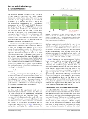
running the Linux OpenSuse 11.3 operating system with Figure 6. Configuration of the jaws and MLC leaves used during
custom-made C/C++ routines. A 25-meter Ethernet irradiation. The field size defined by the MLC and the jaws was
cable was used to establish the connection with the router 10 mm × 10 mm and 5 mm × 5 mm at the isocenter, respectively. The
inside the treatment room. The total dead time of the data junction between the MLC leaves was offset by 100 mm from the center.
Abbreviation: MLC: Multi-leaf collimator.
acquisition system was approximately 85%.
Once the data were collected during the irradiation, the MLC was positioned to define a field of 10 mm × 10 mm
corresponding counts spectra were constructed. It should at the isocenter. Note that the junction between the leaves
be noted that the information collected by the CAMAC of the same pair of the MLC had an offset of 100 mm from
system during irradiation consists of a data vector for the isocenter, as depicted in the diagram. This arrangement
each channel of the prototype. Each sample in this vector of the jaws and the MLC aimed to minimize the impact of
represents the maximum amplitude value of an event radiation that escapes through the linac head window and
detected by that channel. To build the count profiles, we falls outside the field of interest. The jaws were set to define
first created a histogram of the values obtained for each a field size of 5 mm × 5mm at the isocenter.
of the channels for a given measurement. Each histogram
was divided into 128 bins, with values ranging from 0 to Figure 7 displays the time macrostructure of the linac
2047 (this value was chosen based on the fact that the ADC beam measured with the prototype and acquired with
used in the acquisition has a dynamic range of 11 bits). a PicoScope 2203 oscilloscope (Pico Technology, UK).
The resulting histogram is then fitted to a Gaussian curve Examining the persistence graph obtained from 100
according to the Equation I: waveforms plotted on a time scale that allows two pulses
to be observed simultaneously (left), the period of the
( x− ) 2 macrostructure is 4.85 ms, corresponding to a frequency of
µ
y = A e× 2 σ 2 (I) approximately 206 Hz. From the analysis of a single pulse
where A, μ, and represent the amplitude, mean, and (persistence plot at the middle and average pulse waveform
standard deviation of the Gaussian curve, respectively. This at right), it exhibits a fast rise in amplitude (approximately
procedure was implemented in MATLAB (MathWorks, 0.85 µs), followed by a slower rise (for about 3.25 µs),
Massachusetts, USA), using the fminsearch function to and a sharp decay at around 1.40 µs. After approximately
calculate the best-fit parameters. The profile value for a 5.5 µs, the event approaches values very close to zero and
given channel at a certain irradiation position is then given continues with a gradual decay that persists until around
by the value of μ, obtained from the Gaussian fit. 10 µs (when the signal returns to the baseline).
2.3. Linear accelerator 2.4. Mitigation of the out-of-field radiation effect
The linac used in this experimental study was the It is well established that there exists a background flux of
TrueBeam (Varian Medical Systems, Inc., Palo Alto, photons (and other particles) emanating from the linac
CA, USA) installed in the Radiotherapy Department head. Studies have been conducted to examine the influence
of the Coimbra Hospital and University Center. It was of such out-of-field flux on the development of secondary
operated at 6MV in flattening filter-free mode with a dose oncological diseases. Different types of accelerators yield
11
rate of 800 monitor units per minute (MU/min). A field varying doses outside the treatment field due to differences
size of 5 mm × 5 mm at the isocenter was used. This size in their shielding. The background radiation escaping
12
was achieved by the combined setting of the jaws and from the linac head presents technological challenges for
the multi-leaf collimator (MLC). Figure 6 illustrates the orthogonal ray imaging, as it can lead to signal saturation
configuration used during the irradiation process. The when penetrating the detector. In addition, this out-of-
Volume 2 Issue 3 (2024) 5 doi: 10.36922/arnm.4099