
Page 83 - ARNM-2-3
P. 83
Advances in Radiotherapy
& Nuclear Medicine OrthoCT experimental proof of concept
Figure 7. Macrostructure of the linear accelerator (linac) beam measured with the prototype. Left and middle: persistence graph obtained from 100
waveforms with different time scales. The period between beam pulses is 4.85 ms. Right: impulse obtained from the average of 100 waveforms.
field flux significantly diminishes the signal-to-noise ratio,
potentially compromising the ability to detect the signal of
interest originating from radiation scattered on the target.
Eliminating the background escaping the linac head poses
a challenge. However, its impact on the detector can be
mitigated by the introduction of shielding material. To
13
this end, several blocks of Cerrobend and lead (with a
density of 9.38 g/cm and 11.34 g/cm , respectively) were
3
3
positioned around the detector. Various configurations
were tested, and the one yielding the best results is
illustrated in Figure 8. Approximately 315 kg of shielding
material was used.
To analyze the influence of the shielding on the
performance of the prototype, preliminary measurements
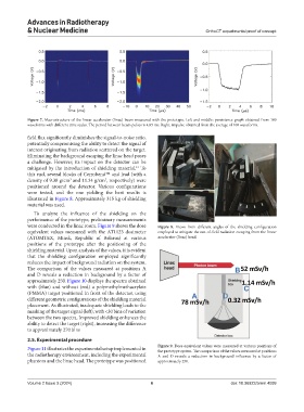
were conducted in the linac room. Figure 9 shows the dose Figure 8. Views from different angles of the shielding configuration
equivalent values measured with the AT1123 dosimeter employed to mitigate the out-of-field radiation escaping from the linear
(ATOMTEX, Minsk, Republic of Belarus) at various accelerator (linac) head.
positions of the prototype after the positioning of the
shielding material. Upon analysis of the values, it is evident
that the shielding configuration employed significantly
reduces the impact of background radiation on the system.
The comparison of the values measured at positions A
and D reveals a reduction in background by a factor of
approximately 250. Figure 10 displays the spectra obtained
with (blue) and without (red) a polymethylmethacrylate
(PMMA) target positioned in front of the detector, using
different geometric configurations of the shielding material
placement. As illustrated, inadequate shielding leads to the
masking of the target signal (left), with <30 bins of variation
between the two spectra. Improved shielding enhances the
ability to detect the target (right), increasing the difference
to approximately 270 bins
2.5. Experimental procedure
Figure 11 illustrates the experimental setup implemented in Figure 9. Dose equivalent values were measured at various positions of
the prototype system. The comparison of the values measured at positions
the radiotherapy environment, including the experimental A and D reveals a reduction in background influence by a factor of
phantom and the linac head. The prototype was positioned approximately 250.
Volume 2 Issue 3 (2024) 6 doi: 10.36922/arnm.4099