
Page 86 - ARNM-3-1
P. 86
Advances in Radiotherapy
& Nuclear Medicine Cone beam-focused GK dosimetric analysis
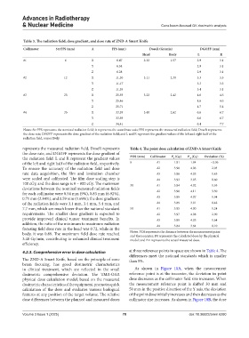
Table 3. The radiation field, dose gradient, and dose rate of ZND‑A Smart Knife
Collimator Str FFS (mm) A FFS (mm) DoseR (Gy/min) DGOFF (mm)
Head Body L R
#1 6 X 6.47 2.32 1.57 2.9 3.1
Y 6.54 2.9 3.1
Z 6.28 2.9 3.1
#2 12 X 11.30 3.11 2.30 3.3 3.3
Y 11.17 3.3 3.3
Z 11.55 3.4 3.1
#3 25 X 25.59 3.22 2.42 4.6 4.6
Y 25.46 4.6 4.6
Z 25.71 4.7 5.4
#4 35 X 33.59 3.48 2.62 6.6 6.7
Y 33.59 6.6 6.7
Z 34.41 6.4 7.7
Notes: Str FFS represents the nominal radiation field; A represents the coordinate axis; FFS represents the measured radiation field; DoseR represents
the dose rate; DGOFF represents the dose gradient of the radiation field; and L and R represent the gradient values of the left and right half of the
radiation field, respectively.
represents the measured radiation field, DoseR represents Table 4. The point dose calculation of ZND‑A Smart Knife
the dose rate, and DGOFF represents the dose gradient of
the radiation field. L and R represent the gradient values POS (mm) Collimator P (Gy) P (Gy) Deviation (%)
0
m
of the left and right half of the radiation field, respectively. 0 #1 1.91 1.84 −3.36
To ensure the accuracy of the radiation field and dose #2 3.98 4.06 2.03
rate data acquisition, the film and ionization chamber #3 3.98 4.05 1.85
were scaled and calibrated. The film dose scaling step is #4 3.93 3.95 0.60
100 cGy, and the dose range is 0 – 800 cGy. The maximum 30 #1 3.94 4.02 1.95
deviations between the nominal measured radiation fields #2 3.98 4.11 3.30
for each collimator were 0.54 mm (9%), 0.83 mm (6.92%),
0.71 mm (2.84%), and 0.59 mm (1.69%); the dose gradients #3 3.99 4.07 1.94
of the radiation fields were 3.1 mm, 3.4 mm, 5.4 mm, and #4 3.89 3.91 0.48
7.7 mm, which are much lower than the national standard 50 #1 3.95 4.00 1.24
requirements. The smaller dose gradient is expected to #2 3.97 4.08 2.90
provide improved clinical tumor treatment benefits. In #3 3.99 4.05 1.64
addition, the ratio of the minimum to maximum radiation #4 3.84 3.84 0.10
focusing field dose rate in the head was 0.72, while in the
body, it was 0.89. The maximum field dose rate reached Notes: POS represents the distance between the measurement point
and the isocenter; P0 represents the calculated dose by the physical
3.48 Gy/min, contributing to enhanced clinical treatment model; and Pm represents the actual measured dose.
efficiency.
4.2.3. Comprehensive error in dose calculation at three reference points in space are shown in Table 4. The
differences meet the national standards which is smaller
The ZND-A Smart Knife, based on the principle of cone than 5%.
beam focusing, has good dosimetric characteristics
in clinical treatment, which are reflected in the small As shown in Figure 10A, when the measurement
dosimetric comprehensive deviation. The TMR-OAR reference point is at the isocenter, the deviation in point
physical dose calculation model, based on the measured dose decreases as the collimator field size increases. When
dosimetric characteristics of the equipment, promotes quick the measurement reference point is shifted 30 mm and
calculation of the dose and evaluates various biological 50 mm in the positive direction of the Y axis, the deviation
features at any position of the target volume. The relative of the point dose initially increases and then decreases as the
dose differences between the planned and measured doses collimator size increases. As shown in Figure 10B, the dose
Volume 3 Issue 1 (2025) 78 doi: 10.36922/arnm.6280