
Page 68 - DP-1-1
P. 68
Design+ Defect-oriented BIST for AMS circuits
the International Test Conference 2020 (ITC’20). In this designed transition threshold voltages, were used as
15
work, since the circuit was already quite simple, there monitors for detecting the defects.
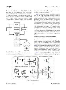
was no need to break the circuit into smaller subcircuits. Figure 2 presents the process for the defect-oriented
We used the intentional offset injection circuitry as an BIST for SAR ADC based on the proposed concept. The
injector circuit for operational amplifier defect-oriented circuit was first divided into three smaller subcircuits:
BIST. 15,16 Digital window comparators, which are simply comparator, capacitive digital to analog converter (DAC)
a combination of different inverters with specifically and binary switches, and sampling switch. Crucial nodes
for each of these three subcircuits were then identified, e.g.,
the input of the comparator, or top plate of binary capacitive
array. For SAR ADC, there is no need for any external
injector circuits. Using the operation of the circuit itself, a
test mode was developed for each of the three subcircuits
that will be discussed in depth in the later sections. Finally,
comprehensive simulations were performed for each of
these subcircuits, testing the robustness and correctness of
the test methods for each defect. Utilizing the presented
approach, results showed a 100% defect coverage for SAR
ADC.
2.2. High-speed defect simulation and defect
universe
The six common defects – open drain, open gate, open
source, gate-drain short, gate-source short, and drain-
source short – are considered for defect coverage in this
work. For fast and accurate simulation, the models in
Figure 3 are used, which are in accordance with the P2427
Standard draft. In these models that we introduced
17
primarily in a previous paper, defects are realized by
13
using a specific placement of resistors. The value of these
resistors’ change based on the defect that is being tested.
Figure 2. Developing BIST for SAR ADC
Abbreviations: ADC: Analog-to-digital converter; BIST: Built-in self- Table 1 summarizes the values of these resistors for
test; SAR: Successive approximation register. inducing each of the six defects. For example, R , is a
nml_short
Figure 3. Standard defect models
Volume 1 Issue 1 (2024) 4 doi: 10.36922/dp.4351