
Page 100 - EER-2-1
P. 100
Explora: Environment
and Resource Artificial neural networks
3.3. Electrothermal model The thermal aspect of the model incorporates
3.3.1. Principle of the electrothermal model thermodynamic equations specific to cylindrical cells.
It assumes a single temperature point, where heat is
This study employed a one-dimensional electrothermal generated at a particular location on the cell’s surface,
model, utilizing a semi-empirical approach within the defined by its specific heat capacity and mass. Heat is
MATLAB/Simulink® 2024 platform. The model is designed then dissipated from the cell’s surface to the surrounding
to simulate the electrical and thermal behavior of the environment. A heat balance equation at the cell surface
battery cell through two main modules: the electrical and is applied to model the thermal exchange between the
thermal components. The electrical module determines cell and the ambient environment, as described by the
the SoC by analyzing electrical parameters, while the following thermodynamic equations: 53
thermal module estimates the cell’s temperature using heat
generation equations. dU cell dT
t
mCp.
t
gen
The electrical model (Figure 6) is based on the second- dt = Q () − Q () = . dt
loss
order Thevenin model, 49,50 consisting of a voltage source Q = R ( . I ) 2 (IV)
in series with two parallel RC networks and an ohmic Q = = Q gen = h int S . batt .( T −T )
resistor. According to the ECM, the output voltage of the loss conv conv area cell amb
Li-ion battery cell is calculated as the voltage drop across
the OCV, the ohmic resistance (R ), the concentration
0
polarization resistance (R C circuit), and the activation where U , the internal energy, is the total energy
cell
1
1
polarization resistance (R C circuit). The resulting output contained by a thermodynamic system (J); Q is the
gen
2
2
voltage is then computed using the following equation: 7,13 generating heating rate (W) in the corresponding element;
and Q is the heat losses of the corresponding element
V = OCV – R I – R I – R I (II) loss
cell 1 1 2 2 0 batt (W). C is the specific heat of the cell (kJ/kg.K) and m is the
p
where I batt is the flowing current in the battery (A). mass of the cell (kg). The thermal model operates under
Thereafter, the SoC is determined by the Coulomb- the following assumptions:
counting method and is defined in: 51,52
A
1
SoCSoC= 0 − C init ∫ I batt dt (III)
where SoC represents the initial SoC of the cell. C
0
init
is defined as the initial capacity (Ah), which is assumed
to be dependent on temperature and influenced by the
applied current and degradation. In Equation II, the OCV
was directly obtained from the OCV test, as outlined in
Section 2.2. The resistances, which vary with temperature,
SoC, and aging, were determined using a parameter
extraction algorithm. Based on the HPPC test results, a B
fitting algorithm within Batalyse was employed to match
simulation data with experimental results, allowing for
the extraction of individual parameters. These extracted
parameters were then mapped into lookup tables within
the MATLAB/Simulink® environment.
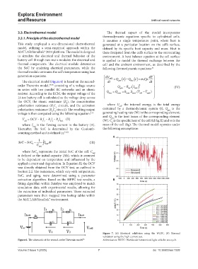
Figure 7. (A) Electrical validation using the WLTC. (B) Thermal
validation using the high-current test.
Figure 6. The schematic of the second-order Thévenin model 55 Abbreviation: WLTC: Worldwide harmonized light vehicles test cycle.
Volume 2 Issue 1 (2025) 7 doi: 10.36922/eer.7228