
Page 449 - IJB-10-1
P. 449
International Journal of Bioprinting Bioactive scaffold for necrosis bone repair
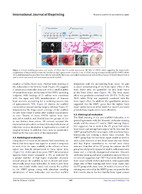
Figure 4. Animal modeling procedure and results. (A) Flow chart of animal experiments. (B) MRI of ONFH rabbits suggesting the characteristic
manifestation of femoral head necrosis, the “double-line sign” (green arrow). Scale bar: 2 cm. (C) H&E staining of normal rabbits and (D) ONFH rabbits.
(E) Scaffold implantation procedure; bone defect is indicated by blue arrow, and scaffold implantation is indicated by red arrow. (F) Rabbit femoral head at
week 8, which was covered with bone tissue outside the scaffold.
number of hollow bone traps. Normal H&E staining of integration with the surrounding bone tissue. To gain
the trabeculae in the femoral head (Figure 4D) suggests a clearer understanding of the bone repair effect in the
a continuous trabecular structure with a small number bone defect area, we quantified the new bone tissue
of vacant bone traps. At the time of the ONFH modeling in the bone defect area (Figure 5B). The bone repair
endpoint, MRI findings of 23 rabbits were consistent effect was positively correlated with BV/TV, Tb.Th, and
with the signs and MRI manifestations of femoral Tb.N, while Tb.Sp was negatively correlated with the
head necrosis, accounting for a modeling success rate bone repair effect. In addition, the quantitative analysis
of approximately 76%. Figure 4E depicts the scaffold suggested that the HBPT group had the highest bone
implantation process during surgery, whereas Figure 4F repair performance at either week 4 or week 8 and could
demonstrates the large-extent coverage of the scaffold promote bone regeneration more effectively.
by new bone tissue 4 weeks after scaffold implantation
in vivo. Twenty of these ONFH rabbits were then 3.5. Histological evaluation
selected at random and divided into two groups of five The H&E staining of the peri-scaffold trabeculae is in
at two distinct time points. All animals survived the general agreement with the Masson’s trichrome staining
implantation procedure without showing indications of results and the micro-CT results. H&E staining (Figure
infection, such as ulceration or septicemia as a result of 6A) suggested that at week 4, the PT group had sparse
surgical incision. In addition, there were no unintended bone tissue and average bone repair, but by this time, the
fatalities by the conclusion of the experiment. HBPT group had better bone repair, with new bone tissue
intersecting and forming a dense bone structure. The
3.4. Radiological evaluation HBPT group had the best bone repair results at week 8,
Using micro-CT scans of the femoral head specimens, we with a clear structure of new bone tissue that was thicker
found that bone repair was superior at week 8 compared and had higher resemblance to normal bone tissue
to week 4 for the same scaffold, as the efficacy of bone structure than that of the PT group. In contrast, the PT
repair was directly proportional to bone repair time group was still poorly repaired at week 8, with sparse bone
(Figure 5A). At the same time point, HBPT demonstrated tissue and a relatively disorganized structure. Masson’s
superior bone repair compared to PT, as indicated by trichrome staining and semi-quantitative analysis (Figure
a greater number of high-signal trabecular structure 6A and 6B) suggested that HBPT had more obvious new
wound around the scaffold, as well as denser and more bone tissue at both week 4 and week 8, with significantly
structurally intact bone trabeculae. At week 8, new bone larger area of blue staining and better bone repair than
tissue was clearly visible inside and outside the scaffold the PT group at the same time. At week 8, the area of blue
in the HBPT group, along with abundant crawling staining was reduced in the HBPT group compared to the
substitution of bone trabeculae and excellent scaffold first 4 weeks, due to the fact that the bone repair around
Volume 10 Issue 1 (2024) 441 https://doi.org/10.36922/ijb.1152