
Page 51 - IJB-2-1
P. 51
Elizabeth V. Koudan, Elena A. Bulanova, Frederico DAS Pereira, et al
at 37ºC in a humidified atmosphere with 5% CO 2. . USA). Tissue spheroids viability data were analyzed
NHDF spheroids were visualized by inverted light using GraphPad Prism software (GraphPad Software,
microscopy (Eclipse TS100, Nikon, Japan). Spheroid Inc., La Jolla, CA).
diameters were measured using ImageJ software. Dia-
meter distribution plots were analyzed using Graph- 2.9 Scanning Electron Microscopy
Pad Prism software (GraphPad Software, Inc., La Jolla, Electrospun polyurethane matrix was gold-coated us-
CA). 4 days tissue spheroids have been used for their ing ion coater (IB-3, EIKO, Japan) and the structure of
robotic placing on electrospun polyurethane matrix. the microfilaments was characterized by scanning
electron microscope (SEM) (JSM-6510LV). Samples
2.5 Patterning of Tissue Spheroids
were observed at 30 kV accelerating voltage. The sam-
The suspension of tissue spheroids have been placed ples of tissue spheroids on electrospun polyurethane
according to digital model (linear and hexagonal order) matrix were fixed with 2.5% glutaraldehyde/0.1Mca-
on the surface of electrospun polyurethane matrix us- codylate buffer, dehydrated through ethanol series and
ing original 3D bioprinter Fabion with conus-like pi- then were dried in a critical point dryer (HCP-2, Hita-
pets, allowing precision placing of tissue spheroid one chi Koki Co. Ltd., Japan). The samples are mounted
by one. on a stub of metal with adhesive, coated with gold us-
ing ion coater (IB-3, EIKO, Japan) and then observed
2.6 Kinetics of Tissue Spheroids Spreading under the microscope JSM -6510 LV (JEOL, Japan).
The kinetics of tissue spheroids spreading on electros- 2.10 Statistical Analysis
pinning polyurethane matrix was evaluated by mea-
suring the spheroid’s diameter in the course of attach- The statistical analysis was performed using software
ing and spreading. Several experiments were per- GraphPad Prism (USA).
formed. In each experiment the following time points 3. Results
were evaluated: 4 hours, 24 hours, 48 hours, 4 days
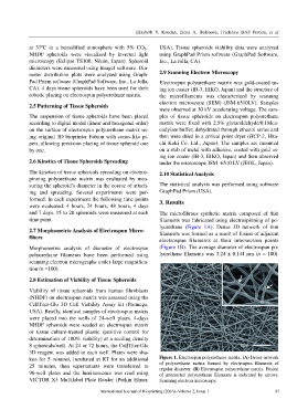
and 7 days. 15 to 20 spheroids were measured at each The microfibrous synthetic matrix composed of thin
time point. filaments was fabricated using electrospinning of po-
lyurethane (Figure 1A). Dense 3D network of thin
2.7 Morphometric Analysis of Electrospun Micro- filaments was formed as a result of fusion of adjacent
fibers
electrospun filaments at their intersection points
Morphometric analysis of diameter of electrospun (Figure 1B). The average diameter of electrospun po-
polyurethane filaments have been performed using lyurethane filaments was 3.24 ± 0.144 µm (n = 100).
scanning electron micrographs under large magnifica-
tion (n =100).
2.8 Estimation of Viability of Tissue Spheroids
Viability of tissue spheroids from human fibroblasts
(NHDF) on electrospun matrix was assessed using the
CellTiter-Glo 3D Cell Viability Assay kit (Promega,
USA). Briefly, identical samples of electrospun matrix
were placed into the wells of 24-well plates. 4-days
NHDF spheroids were seeded on electrospun matrix
or tissue culture-treated plastic (positive control for
determination of 100% viability) at a seeding density
8 spheroids/well. At 24 or 72 hours, the CellTiter-Glo
3D reagent was added to each well. Plates were sha-
ken for 5 minutes, incubated at RT for an additional Figure 1. Electrospun polyurethane matrix. (A) Dense network
25 minutes, then supernatants were transferred to of polyurethane matrix formed by electrospun filaments of
regular diameter. (B) Electrospun polyurethane matrix. Fusion
96-well plates and the luminescence was read using of intersected polyurethane filaments is indicated by arrows.
VICTOR X3 Multilabel Plate Reader (Perkin Elmer, Scanning electron microscopy.
International Journal of Bioprinting (2016)–Volume 2, Issue 1 47