
Page 50 - IJB-2-2
P. 50
Rheological study on 3D printability of alginate hydrogel and effect of graphene oxide
materials were used without further purification. on the fluid mechanics [27] , the viscosity is a function
Aqueous solutions of alginate with various concen- of shear rate. At a constant volume flow rate, the linear
trations (2, 4, 6, 8 and 10 wt.%) were prepared using flow rate in a pipe will change when the cross section
deionized water from a Millipore water purifier. Then, area of the pipe is changed. Therefore, the linear flow
calcium chloride solutions with various molar frac- rate will change due to the change in the cross section
tions were added to each solution of alginate to obtain area from the syringe to the nozzle, which also results
alginate hydrogels with various CaCl 2 contents. In in a change in the shear rate. Shear rate is an important
order to study the effect of GO on alginate hydrogels, factor for an extrusion based printer. In this study, the
alginate composite hydrogels filled with various GO range of shear rates in the syringe is estimated from a
contents were prepared as follows. First, the suspen- given piston moving speed of the 3D printer.
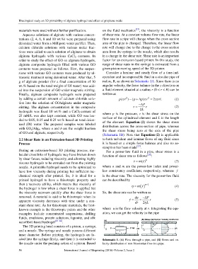
sions with various GO contents were produced by ul- Consider a laminar and steady flow of a time-ind-
trasonic treatment using deionized water. After that, 5 ependent and incompressible fluid in a circular pipe of
g of alginate powder (for a final concentration of 10 radius, R, as shown in Schematic 1A. Since there is no
wt.% based on the total weight of DI water) was add- angular velocity, the force balance in the z direction on
ed into the suspension of GO under magnetic stirring. a fluid element situated at a radius r (0 < r < R) can be
Finally, alginate composite hydrogels were prepared written as
2
by adding a certain amount of calcium chloride solu- ( p π r 2 )(p− +∆ ) p π r = 2τπ rL (1)
tion into the solution of GO/alginate under magnetic −∆ P
stirring. The alginate concentration in the composite τ = r (2)
hydrogels was fixed 10 wt.% and a CaCl 2 content of 2L
25 mM/L was also kept constant, while GO was loa- where p is the pressure, τ is the shear stress on the
surface of the cylindrical element and L is the length
ded to 0.05, 0.15 and 0.25 wt.% based on total deion-
ized (DI) water. The prepared samples were labeled of the element. Equation (2) shows the shear stress
with GO a/Alg b, where a and b are the weight fraction distribution across the cross-section of pipe, whereas
the shear stress being zero at the axis of the pipe
of GO and alginate, respectively.
(Schematic 1B). Note that Equation (2) is applicable
2.2 Shear Rate in an Extrusion-based 3D Printing to both turbulent and laminar flows of any fluid since
Process it is based on a simple force balance and also no as-
sumption has been made [27] .
During an extrusion-based 3D printing process, mo- For a power-law fluid in a pipe, shear stress is a
lecular crosslinks of hydrogels may have broken down function of shear rate as follows [28] :
by shear forces, reducing viscosity, and allowing highly n
()γ =
viscous hydrogels to be extruded out from the printing τ m (3)
nozzle. A printable hydrogel needs to be optimized to where n and m are the power-law index and power-
have low viscosity during printing but sufficient me- law consistency coefficient, respectively, whereas γ
chanical strength after printed. So, it is ideal for a is the shear rate. The viscosity for the power-law fluid
printed hydrogel to have a thixotropic property and can be described by
then a recovery ability, which means that viscosity of η = m ( ) γ n− 1 (4)
the hydrogel is low when a shear force is applied but
the viscosity recovers quickly after the shear force is So, the shear rate can be written as
removed. A material is said to be thixotropic when its du −∆ P
apparent viscosity decreases with time under a con- γ = dr = 2 L r (5)
η
stant shear rate. As for thixotropic materials, the best-
known example is the thixotropic paints and the other where u is the flow velocity at r. Integrating the equ-
examples include concentrated suspensions, drilling ation, we can get the velocity in the pipe
fluids, emulsions, protein solutions, laponite, and silk
nanofibril-based hydrogel [23–26] .
The 3D printing head consists of a piston, a syringe,
and a nozzle. The syringe and nozzle possess different
inner diameter. Before printing, the hydrogels are lo-
aded into the syringe firstly, and then it is extruded to Schematic 1. (A) Flow through a pipe, and (B) Stress and ve-
the nozzle under the pushing action of a piston. Based locity distribution of non-Newtonian flow in a pipe.
56 International Journal of Bioprinting (2016)–Volume 2, Issue 2