
Page 74 - IJB-2-2
P. 74
Producing hip implants of titanium alloys by additive manufacturing
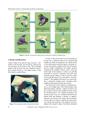
Figure 2. Sequence of operations used to produce an implant via additive manufacturing.
In order to take into account severe deformations of
3. Results and Discussion the hip bone, a physical model of the acetabular hip
Using CT-data of the patient’s bone structure, a 3D- implant was made out of polymer clay, which consid-
model of the hip bone was formed by matching the ers the deformations and future points of bearing. Af-
size and form of the patient’s bone. The polyamide ter that, the polymer implant model was 3D-scanned
model of the hip bone was then 3D-printed using a and the implant configuration was further designed
SLS machine (Figure 3). The build accuracy of the considering the implant’s rotation center. Using the
SLS model is around 100 µm. CAD-model of the implant, its surface was partially
texturized to increase its roughness and create areas
with high specific surface in order to increase contact
surface with the human bone and improve osseointe-
gration [28] . The obtained CAD-model was used to pro-
duce a polyamide implant model, simulating endo-
prosthesis replacement with the made models.
The CAD-model of the implant was positioned rel-
ative to the building plate of the SLM machine using
Materialise Magics software—support structures were
also created to preserve the implant geometry during
the building process. The implant orientation was
chosen in such a way as to minimize thermal stresses
during SLM and minimize a number of supports.
Supports were placed on the surfaces that do not have
special patterns in order to simplify the removal pro-
cess and prevent residuals of the supports from rem-
Figure 3. The polyamide model of the patient’s hip bone. aining on the implant’s surface. The chosen orientation
80 International Journal of Bioprinting (2016)–Volume 2, Issue 2