
Page 515 - IJB-10-2
P. 515
International Journal of Bioprinting Oozing 3D-printed scaffolds for tissue engineering
Gof, geometries we measured the grid thickness instead of JEOL) operated at 10 kV. A total of four regions per scaffold
shred thickness, as they do not possess proper fibers as the were studied (Figure 7).
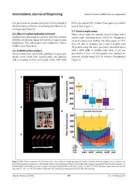
oozing groups (Figure 6).
2.7. Contact angle assays
2.5. Effect of sodium hydroxide treatment Water contact angle was assessed using PLA discs with a
Scaffolds were submerged in a sodium hydroxide solution contact angle measuring system (OCA 15, Dataphysics)
(NaOH, 2 M solution, Sigma-Aldrich) for 15 min at room using the sessile drop method. For these assays, six PLA
temperature. Then, the samples were washed for 5 min in discs (10 mm in diameter and 2 mm in height) were
distilled water three times. 3D-printed using the same parameters described above
2.6. Scaffold surface analysis with a 100% infill. A distilled water drop (3 µL) was
The specimens were coated with a gold layer using an agar generated at 1 µL/s, and photographs were captured for
sputter coater (AGB 7340, AgarScientific) and analyzed posterior analysis using SCA 20 software (Dataphysics)
with a scanning electron microscope (SEM, JSM 5410, (Figure 8).
Figure 6. Fiber thickness analysis. (A–C) Scheme of the fiber thickness measuring setup. (A) Scheme of the five different heights (2, 4, 6, 8, and 10 mm)
for performing fiber measurements. (B) Example of three randomly selected fibers at each height of the sample to perform the fiber thickness analysis. (C)
Representation of five selected points to measure thickness along the fiber (start, mid1, center, and end). (D) Fiber thickness means measurements per
specimen (n = 45, * p < 0.05 by Kruskal–Wallis test). (E) Thickness measurements across the fiber per specimen.
Volume 10 Issue 2 (2024) 507 doi: 10.36922/ijb.2337