
Page 436 - IJB-10-3
P. 436
International Journal of Bioprinting Different modeling of porous scaffolds
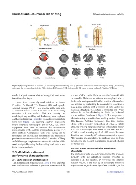
Figure 1. (A) Filling structure in the spine. (B) Thickening structure in the leg bone. (C) Minimal surface units with thickening and filling. (D) Resulting
units under the two modeling strategies. Abbreviations: D, Diamond; F, Fill; G, Gyroid; IW-P, I-graph-wrapped package; P, Primitive; T, Thicken.
mechanical performance while retaining their continuous porous scaffolds. For the filled structure, the ContourPlot3D
transition advantages. command in Mathematica software was employed, where
Hence, four commonly used minimal surfaces— the formula was input, and the offset position of the surface
Primitive (P), Gyroid (G), Diamond (D), and I-graph- was adjusted by controlling the parameter C to achieve a
wrapped package (IW-P)—were selected as the basic units filled porous scaffold with a porosity of 60%. As for the
of minimal porous scaffolds in this study. Maintaining thickened structure, the surface is imported into Wrap
consistent unit size, surface offset, and porosity, two software for surface thickening to obtain the thickened
modeling strategies, filling and thickening, were employed porous scaffolds (as shown in Figure 2). The samples were
on these surfaces (see Figure 1C) to create porous scaffold fabricated using a selective laser melting device (Dimetal
units (see Figure 1D). Scanning electron microscopy, 280, Tridonic Additive Technology Co., Ltd., Canton,
micro-computed tomography (micro-CT), and other China) with a powder composition of Ti6Al4V (TC4)
equipment were used to observe the macro/micro alloy. The printing parameters were as follows: laser power
morphologies of the additive-manufactured porous TC4 of 175 W, powder layer thickness of 30 μm, laser spot size
alloy scaffolds. Compression tests were carried out to of 180 μm, and scanning speed of 1000 mm/s. The scan
investigate the deformation mechanism and mechanical direction was rotated by 67° between consecutive layers.
performance variations of the scaffolds. The effect of filling After printing was completed, the scaffolds were cut from
and thickening strategies on the permeability of the scaffold the substrate and cleaned in ultrasonic baths with ethanol
was investigated by using the descending head method and for further use.
finite element analysis.
2.2. Macro- and microscopic characterization
2. Scaffold fabrication and of scaffolds
performance characterization The scaffold porosity was determined using the drainage
method, with the calculation formula presented in
28
2.1. Scaffold design and fabrication Equation I. In the equation, P represents the sample’s
The mathematical functions from Table 1 were imported porosity (%), m is the mass (g) of the sample immersed
w
into Mathematica software to generate surfaces and fill in pure water, m is the mass (g) of the scaffold, V is the
d d
Volume 10 Issue 3 (2024) 428 doi: 10.36922/ijb.2565