
Page 437 - IJB-10-3
P. 437
International Journal of Bioprinting Different modeling of porous scaffolds
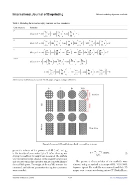
Table 1. Modeling formulas for triply minimal surface structures
Unit structure Formulas
P 2 π π 2 2 π
φ(, ,)xy z = cos x + cos y + cos z = C
3 L 3 L 3 L
G 2 π π 2 π 2 π 2 2π 2π
φ(, ,)xy z = cos x sin y + cos y sin z + cos z sin x = C
3 L 3 L 3 L 3LL 3 L 3 L
D 2 π π 2 2 π π 2 2π 2π
φ(, ,)xy z = cos x cos y cos z − sin x sin y sin z = C
3 L 3 L 3 L 3LL 3 L 3 L
IW-P 2 π π 2 2 π π 2 2π 2π 4π 4π 4π
φ(, ,)xy z = 2 cos x cos y + cos z cos x + cos y cos z − cos x + cos y + cos z = C
3 L 3 L L 3LL 3 L 3 L 3 L 3L 3L
2 π π 2 2 π π 2 2π 2π 4π 4π 4π
φ(, ,)xy z = 2 cos x cos y + cos z cos x + cos y cos z − cos x + cos y + cos z = C
3 L 3 L L 3LL 3 L 3 L 3 L 3L 3L
Abbreviations: D, Diamond; G, Gyroid; IW-P, I-graph-wrapped package; P, Primitive.
Figure 2. Porous scaffold models designed with two modeling strategies.
geometric volume of the porous scaffold (cm ), and ρ m − m
3
w
is the density of pure water (g/cm ). After cleaning and P = w ρ V d ×100% (I)
3
drying the scaffold, its weight was measured. The scaffold w d
was then immersed in a beaker containing ultra-pure water
and secured with a fine thread to ensure complete filling of The geometric characteristics of the scaffolds were
the scaffold’s pores. The weight of the scaffold in water was observed using an optical microscope (OM, VHX-500F,
measured, and relevant parameters during the experiment Keyence, Japan). The scaffolds were scanned, and their 3D
were recorded. images were reconstructed using micro-CT (PerkinElmer,
Volume 10 Issue 3 (2024) 429 doi: 10.36922/ijb.2565