
Page 441 - IJB-10-3
P. 441
International Journal of Bioprinting Different modeling of porous scaffolds
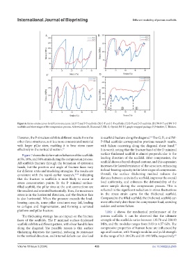
Figure 6. Stress–strain curves for different structures. (A) P-T and P-F scaffolds. (B) G-T and G-F scaffolds. (C) D-T and D-F scaffolds. (D) IW-P-T and IW-P-F
scaffolds and three stages of the compression process. Abbreviations: D, Diamond; F, Fill; G, Gyroid; IW-P, I-graph-wrapped package; P, Primitive; T, Thicken.
However, the P structure exhibits different results from the to scaffold fracture along the diagonal. The G, D, and IW-
46
other three structures, as it is a more concentrated material P-filled scaffolds correspond to previous research results,
with larger pillar sizes, enabling it to bear stress more with failure occurring along the diagonal shear band.
47
effectively in the vertical direction. 43 It is worth noting that the fracture band of the D minimal
Figure 7 shows the deformation behavior of the scaffolds surface-thickened scaffold is almost perpendicular to the
at 5%, 10%, and 30% strain during the compression process. loading direction of the scaffold. After compression, the
All scaffolds fracture through the formation of extrusion scaffold shows a barrel-shaped contour, and this expansion
bands, but the position and angle of fracture faces vary increases the lateral resistance of the structure, enhancing
for different units and modeling strategies. The results are its load-bearing capacity in the later stages of compression.
consistent with the team’s earlier research, 44,45 indicating Overall, the surface thickening method reduces the
that the fracture in scaffolds is most likely to occur at distance between units in the scaffold, improves the overall
stress concentration points. In the P minimal surface- load uniformity, and enhances the deformability of the
filled scaffold, the pillar sizes at the unit connections are entire sample during the compression process. This is
the smallest and oriented horizontally. Thus, the maximum reflected in the significant reduction in stress fluctuations
stress is in the horizontal direction, and the fracture face in the stress–strain curve for the thickened scaffold.
is also horizontal. When the pressure exceeds the load- Compared to the filled scaffold, the thickened scaffold can
bearing capacity, some pillar structures may fail, leading more effectively distribute the compression load, avoiding
to collapse and fragmentation, and forming a serrated sudden and severe failure.
platform and pillar fracture. Table 4 shows the mechanical performance of the
The thickening strategy has an impact on the fracture porous scaffolds. It can be observed that the ultimate
faces of the scaffolds. The P minimal surface-thickened strength of the scaffolds varies between 135.78 and 250.90
scaffold exhibits a different pattern, with shear band failure MPa, and the modulus ranges from 3.03 to 4.57 GPa. The
along the diagonal. The possible reason is that surface compressive properties of human bone are influenced by
thickening disperses the material, reducing its resistance age and location, with Young’s modulus and yield strength
in the vertical direction, and internal defects can also lead in the range of 0.3–30 GPa and 33–193 MPa, respectively.
48
Volume 10 Issue 3 (2024) 433 doi: 10.36922/ijb.2565