
Page 205 - IJB-10-4
P. 205
International Journal of Bioprinting Horsetail-inspired lattice for bone use
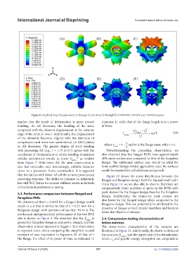
Figure 8. Graphical map of displacement (A through C) and stress (D through F) of 070r040t, 115r025t, and 175r040t samples.
implies that the mode of deformation is more toward Equation II, while that of the flange length is to a power
bending. As AR decreases, the bending of the strut, of three.
compared with the element displacement at the extreme tr ( t − ) 3
2
edge of the strut, is lower. Additionally, the displacement I flange = inner + mt (XI)
12
of the elements becomes aligned with the direction of
compression and more non-symmetrical (in (001) plane)
as AR decreases. The greater degree of strut bending where r inner = and m is the flange mass, with r >>t.
with increasing AR (e.g., r = 1.75 to 0.7) agrees with the Notwithstanding the preceding observations, we
conclusion of Deshpande et al. where bending-dominated also observed that the flanged RVEs have approximately
cellular architecture results in lower E lattice 39 as evident 40% more surface area compared to that of the flangeless
from Figure 7. With lower AR, the strut construction is design. The additional surface area would be ideal for
also less noticeable and, interestingly, exhibits behavior bone scaffold design-related application since the surfaces
closer to a parameter frame construction. It is apparent would be required for cell adhesion and growth.
that the lattices with lower AR exhibit a more pronounced Figure 10 shows the stress distribution between the
stretching response. The ability to enhance an inherently flanged and flangeless design, both for big and small radii.
less stiff BCC lattice to increase stiffness assists in latitude From Figure 10, we are also able to observe that there are
of mechanical performance tuning. comparatively lower numbers of spots on the RVEs with
3.3. Performance comparison between flanged and peak stresses for the flanged design than for the flangeless
flangeless RVEs design. Additionally, the respective peak stresses are
We determined that t = 0.1625 for a flanged design would also lower for the flanged design when compared to the
flangeless design. This can potentially be attributed to the
result in a φ that is similar to that of t = 0.25 mm for a presence of flanges as load transfer members and leads to
flangeless design, with deviation of less than 1% in φ. The better distribution of stresses.
mechanical and geometrical performance of the two RVE
sets is shown in Figure 9. We observed that the E lattice is 3.4. Compression testing characteristics of
greater for flangeless design as opposed to flanged, and this lattice matrices
observation is more apparent at bigger r. This observation The stress–strain characteristics of the samples are
is expected since, when comparing the simplified second illustrated in Figure 11. Additionally, the elastic modulus of
moment of area expression in Equation XI of that of r the matrices, E matrix , and the upper limit of the densification
the flange, the effect of is power of four, as indicated in strain, ε and specific energy absorption are computed as
d
Volume 10 Issue 4 (2024) 197 doi: 10.36922/ijb.2326