
Page 208 - IJB-10-4
P. 208
International Journal of Bioprinting Horsetail-inspired lattice for bone use
0% 10% 20% 30% 40% 50% 60%
BCC
[100]
[110]
[111]
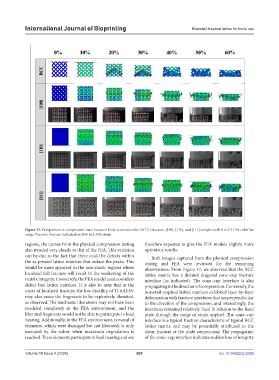
Figure 12. Comparison of compression states between body-centered cubic (BCC) structure, [100], [110], and [111] samples with 0 to 2.5 GPa color bar
range. Fracture lines are indicated on 20% and 30% strain.
regions, the curves from the physical compression testing therefore expected to give the FEA models slightly more
also trended very closely to that of the FEA. This variation optimistic results.
can be due to the fact that there could be defects within Both images captured from the physical compression
the as-printed lattice matrices that reduce the peaks. This testing and FEA were reviewed for the remaining
would be more apparent in the non-elastic regions where observations. From Figure 12, we observed that the BCC
localized full fracture will result in the weakening of the lattice matrix has a distinct diagonal cone–cup fracture
matrix integrity. Conversely, the FEA model used considers interface (as indicated). The cone–cup interface is also
defect-free lattice matrices. It is also to note that at the propagating in the direction of compression. Conversely, the
onset of localized fracture, the low ductility of Ti-6Al-4V horsetail-inspired lattice matrices exhibited layer-by-layer
may also cause the fragments to be explosively liberated, deformation with fracture interfaces that are perpendicular
as observed. The stochastic liberations may not have been to the direction of the compression, and interestingly, the
modeled completely in the FEA environment, and the interfaces remained relatively fixed in relation to the fixed
liberated fragments would not be able to participate in load plate through the range of strain applied. The cone–cup
bearing. Additionally, in the FEA environment, removal of interface is a typical fracture characteristic of typical BCC
elements, which were damaged but not liberated, is only lattice matrix and may be potentially attributed to the
executed by the solver when maximum degradation is shear fracture at the node connections. The propagation
reached. These elements participate in load bearing and are of the cone–cup interface indicates sudden loss of integrity
Volume 10 Issue 4 (2024) 200 doi: 10.36922/ijb.2326