
Page 20 - IJB-5-1
P. 20
Shuai C
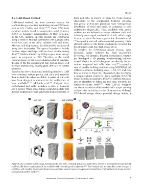
2.1. CAD-Based Method these unit cells, as shown in Figure 2A. Finite element
simulations of the compression behavior indicated
CAD-based method, the most common method for that gyroid architecture presented more homogeneous
scaffolds design, is realized by utilizing various CAD tools, distribution of stress and strain, as compared to cube
such as UG, CATIA, and Pro/E. [33,34] . These CAD tools architecture (Figure 2B). Thus, scaffolds with gyroid
construct models based on constructive solid geometry architecture are believed to expose adherent cells with
(CSG) or boundary representation (B-Rep) principle. relatively more equal mechanical stimuli, which might
In the CSG method, specific models are constructed be more beneficial for bone regeneration. Sercombe et al.
using a series of Boolean operations with standard solid [39] designed a unit cell with octahedral geometry. Finite
primitives, such as the cubic, cylinder, ball, and prism, element analysis of the failure mechanisms revealed that
whereas, in B-Rep method, the solid models are depicted this structure could bear high tensile stress.
using their boundaries. The typical boundaries include To simplify the CAD-based design process, some
vertices, edges, and loops, with no direct relation among dedicated design software has been successfully
them . Models obtained by B-Rep require more storage developed. For instance, Belgium Materialise Company
[35]
space, as compared to CSG. Therefore, as the model has developed a 3D printing pre-processing software
becomes larger or has a more detailed internal structure, named Magics, in which designers can directly instruct
the size of the file containing B-Rep-derived model will various integrated unit cells. Murr et al. reported a
[40]
increase dramatically, causing great difficulty in further case of quickly building scaffolds using MATERAILAS
operation. software elements, including cross 1, G6, G7, and code
Based on the above-mentioned modeling principles, CAD thin, as shown in Figure 2C. Researchers also developed
tools construct various porous unit cells and assemble a computer-aided system for tissue scaffolds (CASTS),
them to build the whole scaffolds. A series of unit cells which included a parametric library of scaffold structures
have been designed to characterize the architecture of and an algorithm to define the pore size, porosity, and
bone scaffolds [36,37] . Melchels et al. designed three surface-to-volume ratio [33,41] . With CASTS, designers
[38]
sophisticated unit cells, including a cube, a diamond, can obtain desired scaffold models with proper porosity
and a gyroid. While space-filling computer models with and pore size by setting a series of parameters. Although
distinct architectures were generated from assemblies of CAD-based design shows powerful design ability, it
A B
C
Figure 2. (A) Computer-aided design-based unit cells with cube, diamond, and gyroid architecture, as well as their assemblies and as-built
scaffolds. (B) Stress-strain curves of the scaffolds with cube and gyroid architecture . The obtained data are described as the averages in
[38]
solid lines with standard deviation in shaded areas, and finite element results are depicted in dashed lines. (C) Materialise Software elements
and designed scaffold models .
[40]
International Journal of Bioprinting (2019)–Volume 5, Issue 1 3