
Page 60 - IJB-6-2
P. 60
Effects of topology optimization in multimaterial 3D bioprinting of soft actuators
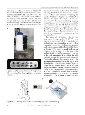
custom-made scaffold, as shown in Figure 7B. bending measurement in this study was carried
The experiment and the computational tool were out using the checkerboard method while features
implemented in MATLAB using a low-cost USB of the webcam were obtained by utilizing the
interface Arduino Nano-based driver hardware Camera Calibration Toolbox in MATLAB to
and a motor driver breakout board for the input minimize the reprojection error as mean pixel
voltage modulation. The recorded images were error of 2.07 . The measurement set up including
[41]
processed through several steps for measuring the a signal generator, two stainless steel electrodes
X and Y value . The calibration of camera for were immersed in 0.2 M NaOH electrolyte
[40]
solution. A paper clip was used to fix one end of
A the soft actuator in the electrolyte solution, letting
the planar bending of the endpoint occur due to
osmotic pressure caused by input signal applied
on electrodes.
The actuator’s hysteresis behavior was
investigated through cyclic “ON-OFF” input
signals. A cyclic signal of ±8 V amplitude was
applied to the electrodes and the average of three
repeated experiments on the bioprinted actuators
made entirely of material 1 and material 2 is shown
in Figure 8. The results revealed the hysteresis
behavior of the actuators over the time of the
applied signal with differences mainly observed
in the peak magnitudes. It is evident that with
repeating cycles the polyelectrolyte actuator’s
B functionality plunges. The actuator absorbs the
moisture and causes swelling, giving rise to large
dilatational strains in the plastic region. The semi-
crystalline nature of the actuator has an influence
on its degradation behavior over bending cycles.
Different concentrations of chitosan content lead
Figure 6. (A) Three-dimensional bioprinting; to different crystallinity which is thought to affect
(B) two-material topology optimized bioprinted the hysteresis behavior of the actuator by changing
actuators. its modulus . The deviation of up to 30% from
[42]
A B
Figure 7. (A) Bending index of the actuator and (B) the measurement set up.
56 International Journal of Bioprinting (2020)–Volume 6, Issue 2