
Page 111 - IJB-8-2
P. 111
Lee, et al.
A B
C D
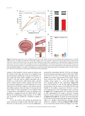
Figure 8. Mechanical properties of the extraluminal anti-reflux diode (EAD) with the DJ stent during insertion and removal. (A and B)
Adhesion forces of joining parts with the DJ stent with a pulling speed of 50 mm/min. Comparison between rough surface (with patterns)
and smooth surface (without patterns). (A) Applied load of specimens with respect to displacement. (B) Maximum average load of each
joining part. Inset: inner surface of the joining parts (with and without patterns). (C) Schematic illustration of removal of the DJ stent with
respect to the positions. Position A is path where the EAD is removing from the ureter to the bladder. Position B is path where the EAD is
removing from the bladder to the urethra. (D) Friction forces between the EAD and silicone rubber with pulling speeds of 50 and 100 mm/
min. Maximum average load at each position with respect to the pulling speed.
contrast, at the interface between grooved patterns and conducted to demonstrate that the EAD does not damage
the surface of the stent, the water can be trapped in the the ureteral mucosa during the removal of DJ stent. While
grooved patterns, and the tips of the grooved patterns can removing the DJ stent, the EAD passes through ureter,
still contact the stent surface, leading to an increase in bladder, and urethra, successively. In this study, friction
friction . This may lead to a higher maximum load of forces between the EAD and silicone rubber, which
[49]
friction in a rough surface with patterns than a smooth emulate urinary organs (i.e., ureter and urethra) wall,
surface without patterns. Taken together, the EAD with were measured using in vitro experiment. Figure 8C
the patterned joining part is more beneficial for strong shows the Positions A and B that represent different
adhesion to the DJ stent compared to that with the joining moving paths from the ureter to the bladder and from the
part without patterns when the stent is inserting into the bladder to the urethra, respectively. Positions A and B
ureter. Based on this experiment, it was confirmed that were implemented in the experimental setup, as shown
a rough surface with patterns is more advantageous for in Figure S3 in Supplementary File. Because the EAD
mechanical coupling between the EAD and DJ stent. is fully surrounded by the ureter at Position A during
Hence, the disadvantage (rough surface) of the FDM- removal, silicone rubber covered whole EAD, as shown
type 3D printer was utilized as a beneficial property in in Figures S3A1 and A2. To mimic the removal through
this study. Position B, the EAD was initially placed outside of silicone
To use the EAD to the patients in practical, the rubber (i.e., bladder) and pulled back through silicone
ureter should not be injured when clinicians remove the rubber (i.e., urethra), as shown in Figures S3B1 and B2.
DJ stents. For this reason, a friction test was additionally It was noteworthy that the EAD was flipped over when
International Journal of Bioprinting (2022)–Volume 8, Issue 2 103