
Page 136 - IJB-8-2
P. 136
3D Printing of Hollow Microneedle Patches
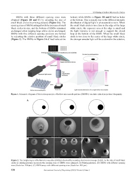
HMNs with three different opening sizes were bottom; while HMNs in Figure 3D and E had no holes
obtained (Figure 2B and C) by adjusting the size of at the bottom. This is mainly due to the different intensity
small black circles in printing pictures (Figure 2A). The distribution of digital light in photosensitive resin. When
opening sizes of HMNs enlarged with the increase of small the small black circle is too close to the edge of the large
black circles in size, and the bottom of HMNs remained white circle, the exposure area at the edge is small and
unchanged when keeping large white circles unchanged. the light intensity is not enough to support the closed
HMNs with five different opening positions are formed loop at the bottom of the HMN. When the small black
by adjusting the relative position of small black circles circle is too close to the center of the large white circle,
(Figure 3). The HMNs in Figure 3A-C had holes at the the stronger annular light will be scattered in the solution,
Figure 1. Schematic diagram of fabrication principle of hollow microneedle patches (HMNPs) via static optical projection lithography.
A
B
C
Figure 2. The morphologies of hollow microneedles (HMNs) observed by scanning electron microscope (SEM). As the size of small black
circles in printing pictures increased, the opening sizes of HMNs were enlarged. (A) Printing pictures. (B) HMNs with different opening
sizes (Scale bar: 300 μm). (C) HMN arrays with different opening sizes (Scale bar: 500 μm).
128 International Journal of Bioprinting (2022)–Volume 8, Issue 2